
The goals this Winter were lofty, so we have had to dial them back substantially as our launch date has been requested to be the week of April 25. We will complete the full refurbishment from the CV joint to the tip of the propeller, replace the steering components in the engine compartment, rebuild the freshwater manifold, and replace several thru-hulls in the engine compartment. The entire aft end of the engine compartment will be refreshed along with new Webasto heaters.
Activities Completed this Session:
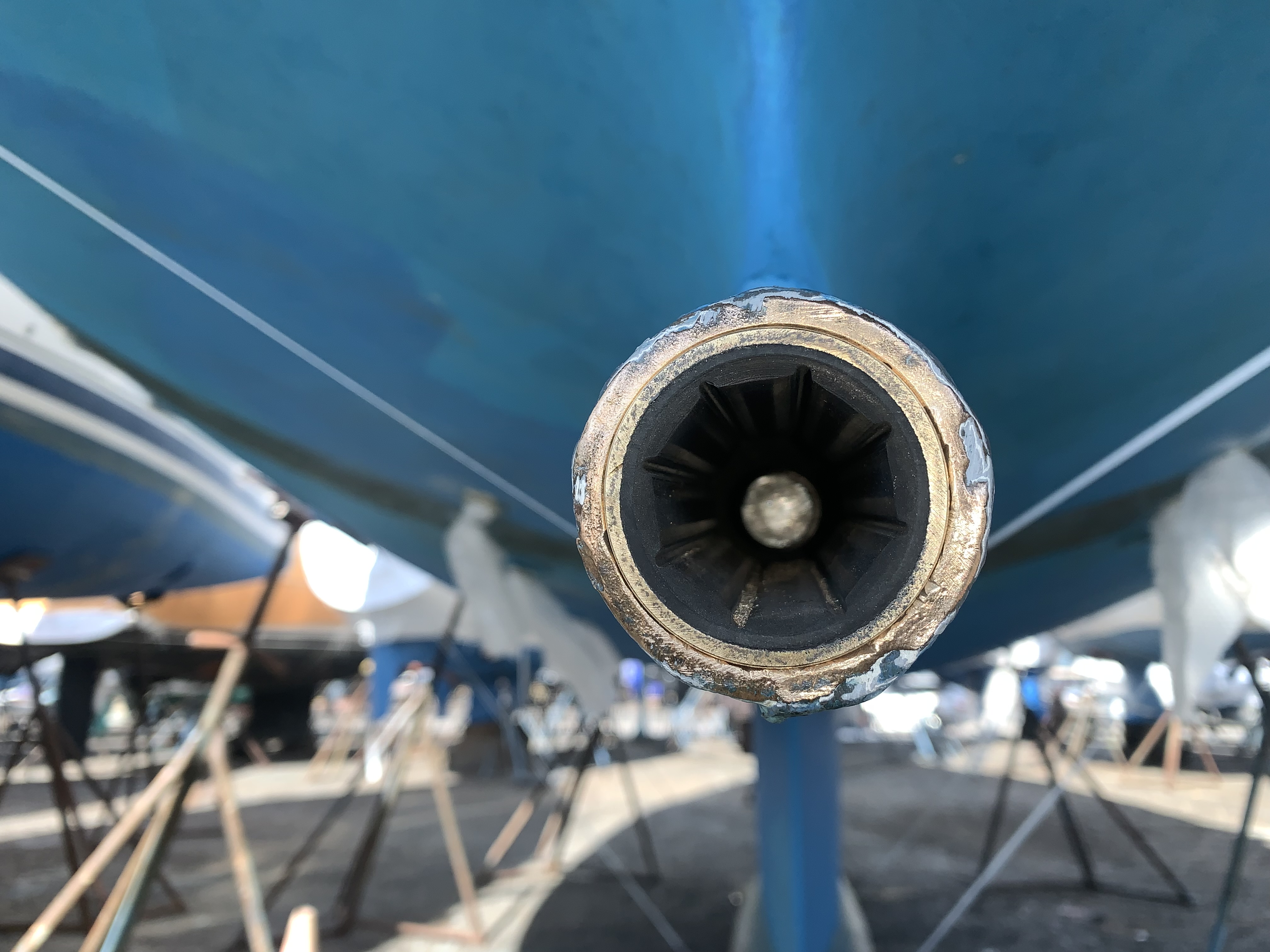
Install cutlass bearing – I decided it was best to replace the cutlass bearing at this time for tip-to-tip refurbishment of the drive train. Cutting out the existing cutlass bearing was brutal. I read up on this and saw other people’s blogs and videos. These examples (you know who you are) made it seem like cutting out their cutlass bearings was relatively easy. That is so gaslighting people! I tried a small hacksaw; that broke. I used a drywall saw with agressive teeth; that got the party started, but it was a lot of work. Then I grabbed a dangerous weapon, my 18v Milwaukee Hack-Zall with an aggressive metal blade.
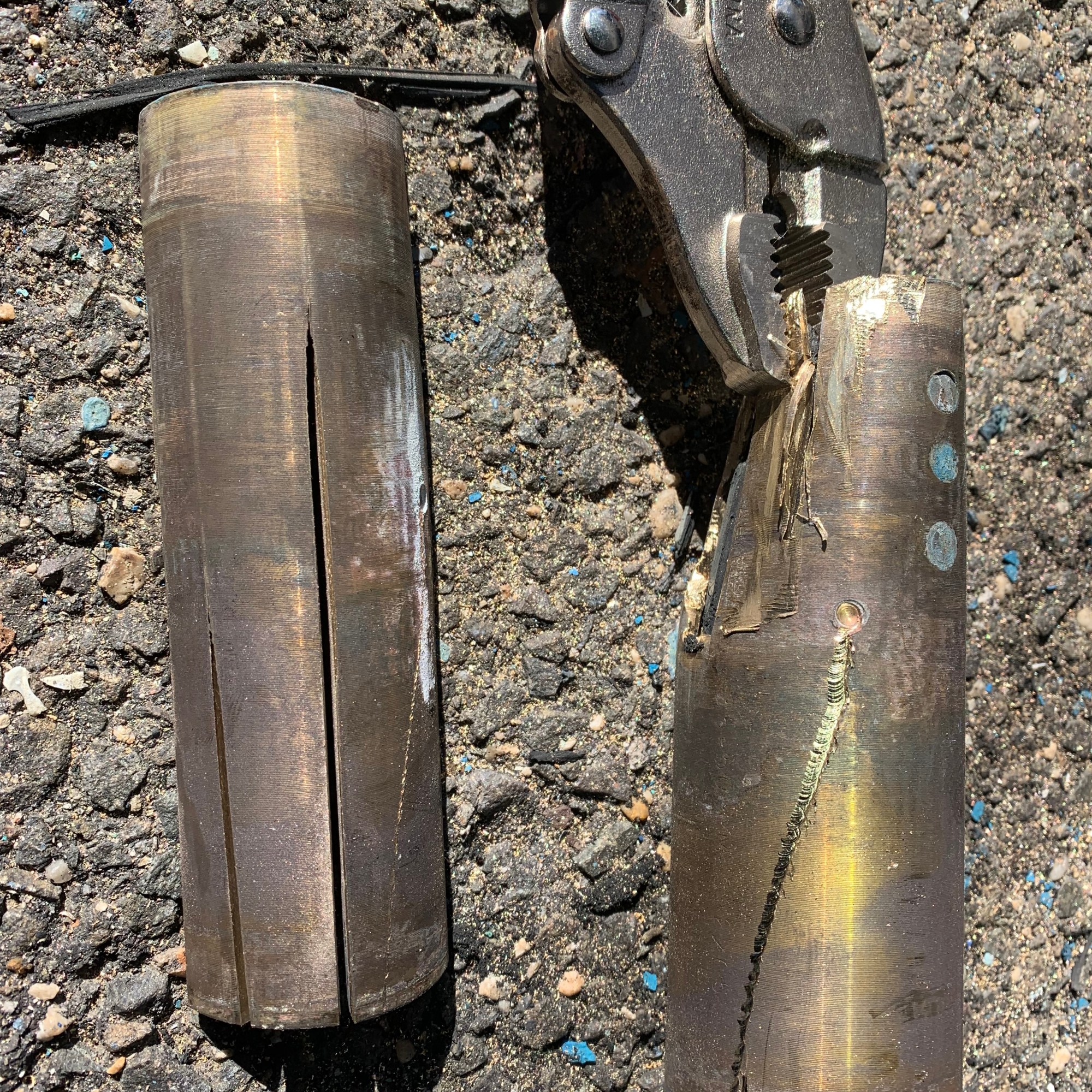
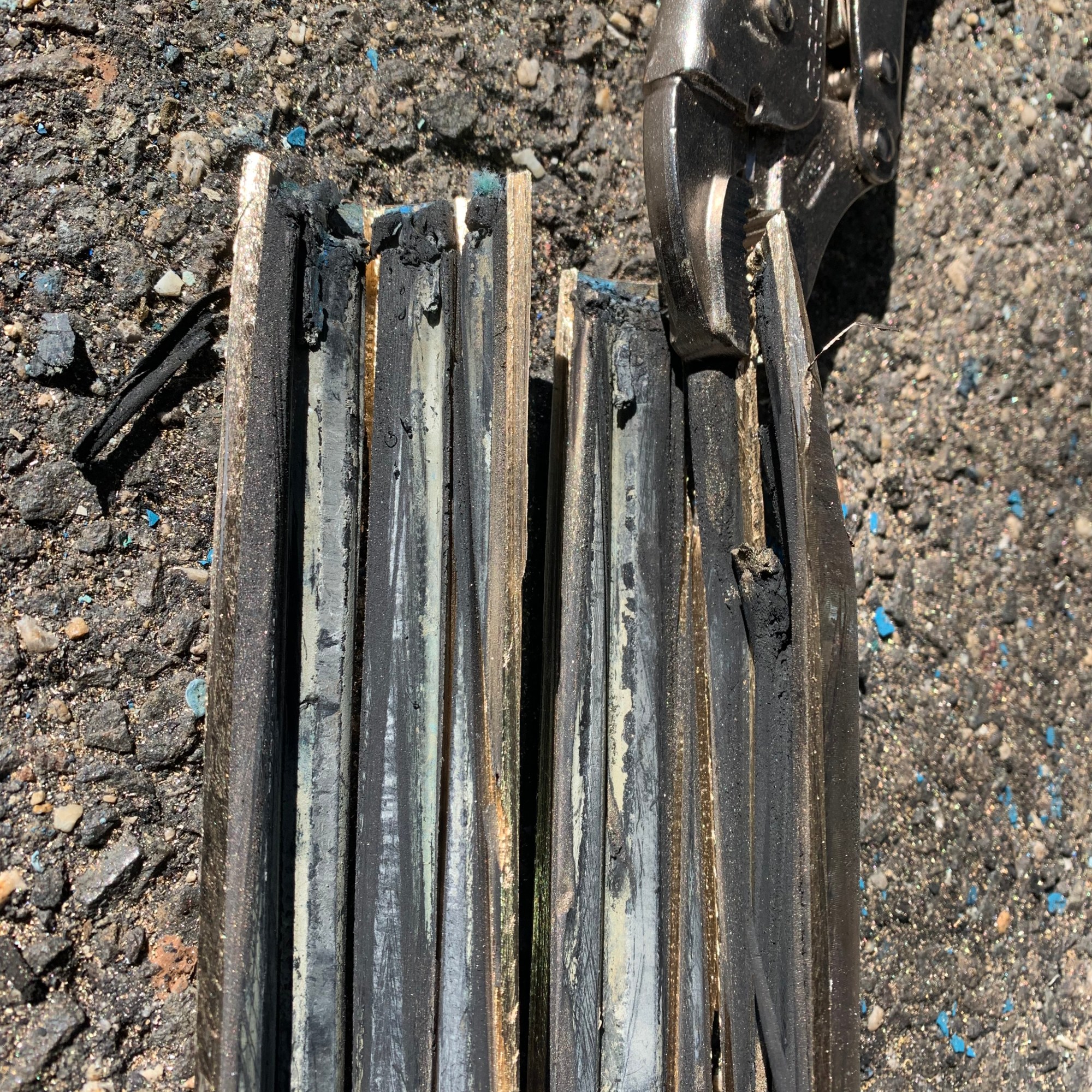
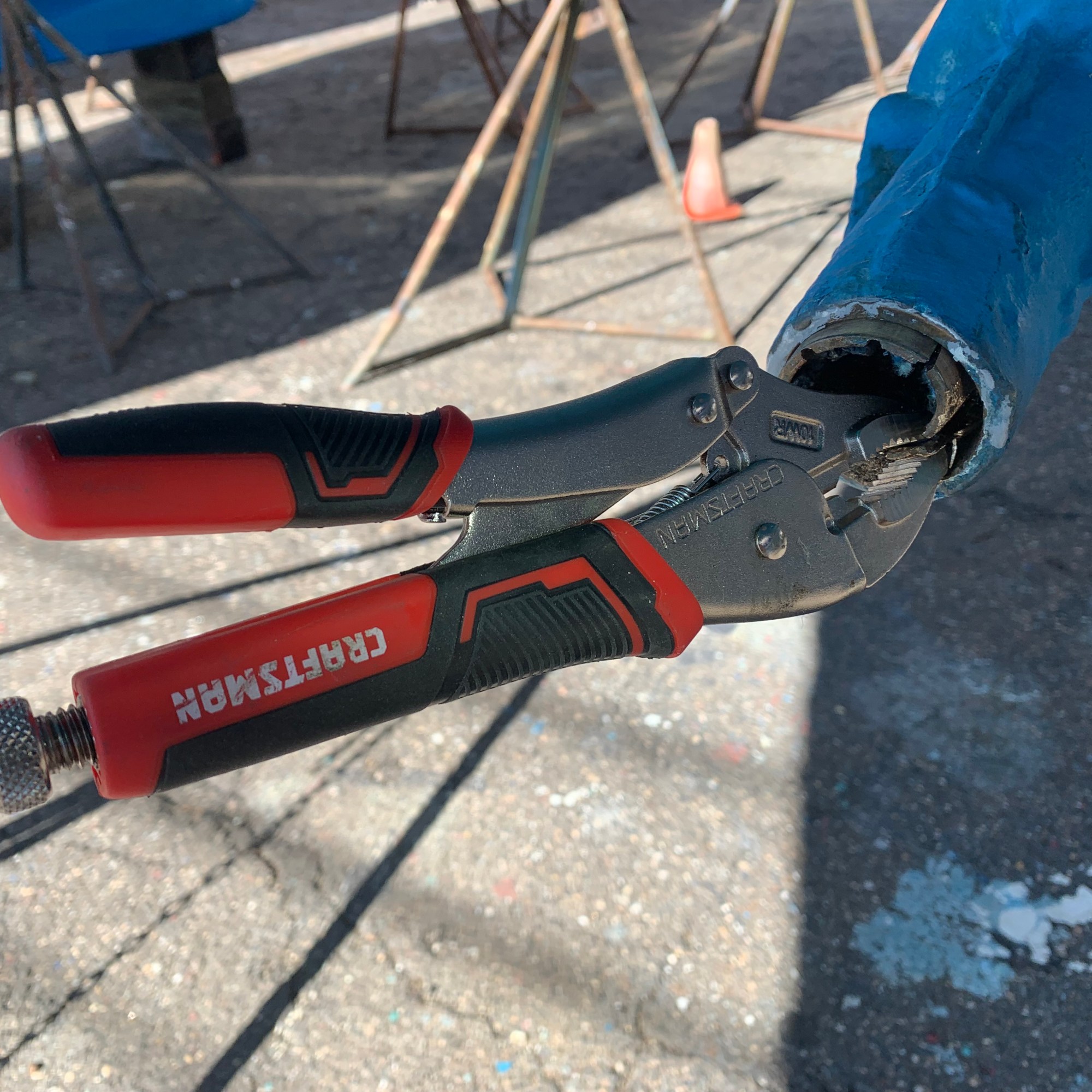
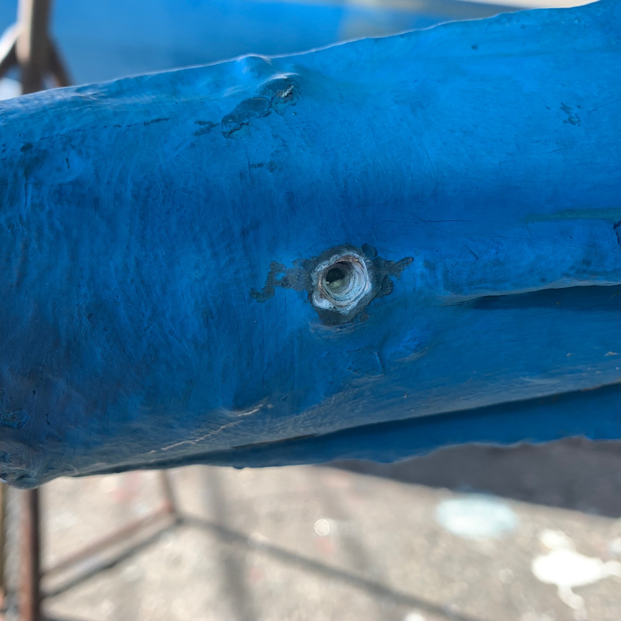
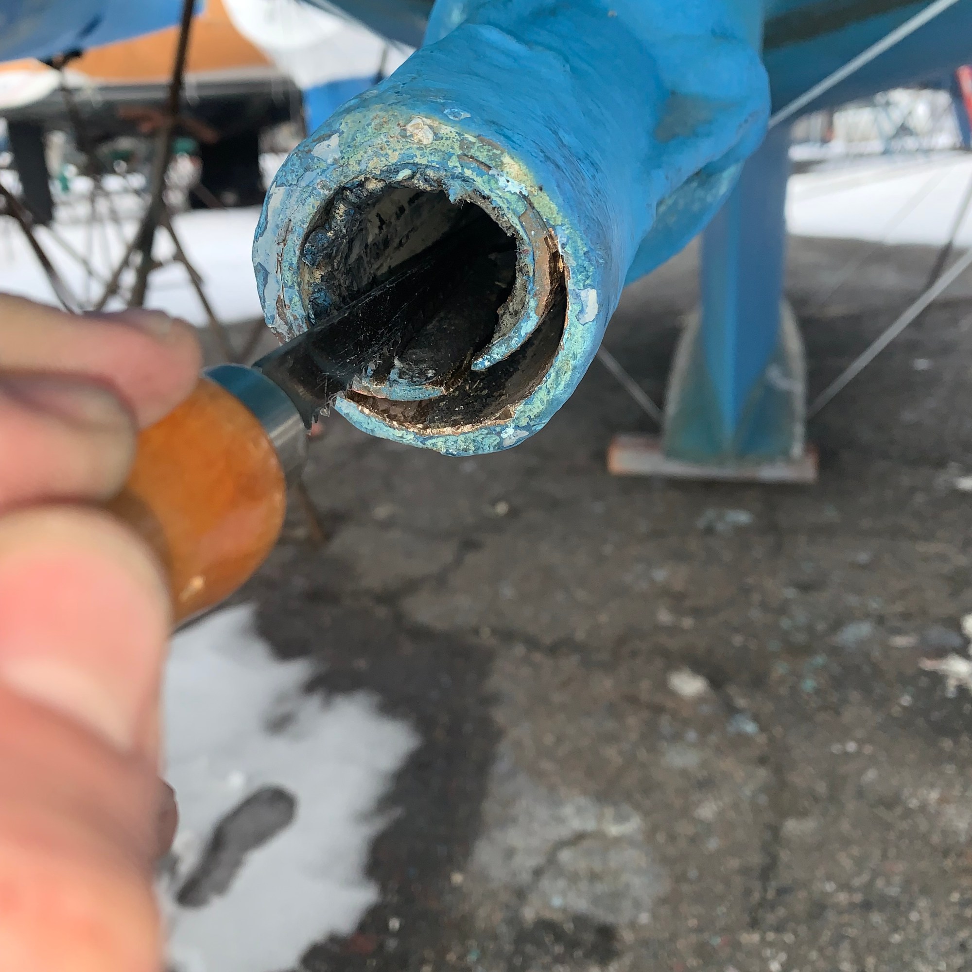
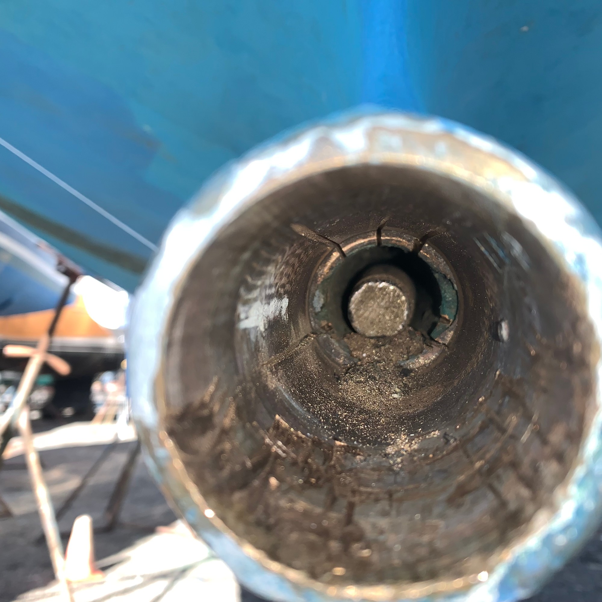
I cut in several channels in the cutlass bearing. That Hack-Zall has a lot of power and deep reach with the right blade. In reflection, I think this was too aggressive as I went a little too deep. I hope that ddecision doesn’t come back to haunt me in the future. Finally, after 4-5 end-to-end cuts, I was able to forcibly remove the remnants of the bearing. I backed off the 3/32″ hex screws on the sides of the housing, and the bearing came out. There wasn’t much left of it that’s for sure.
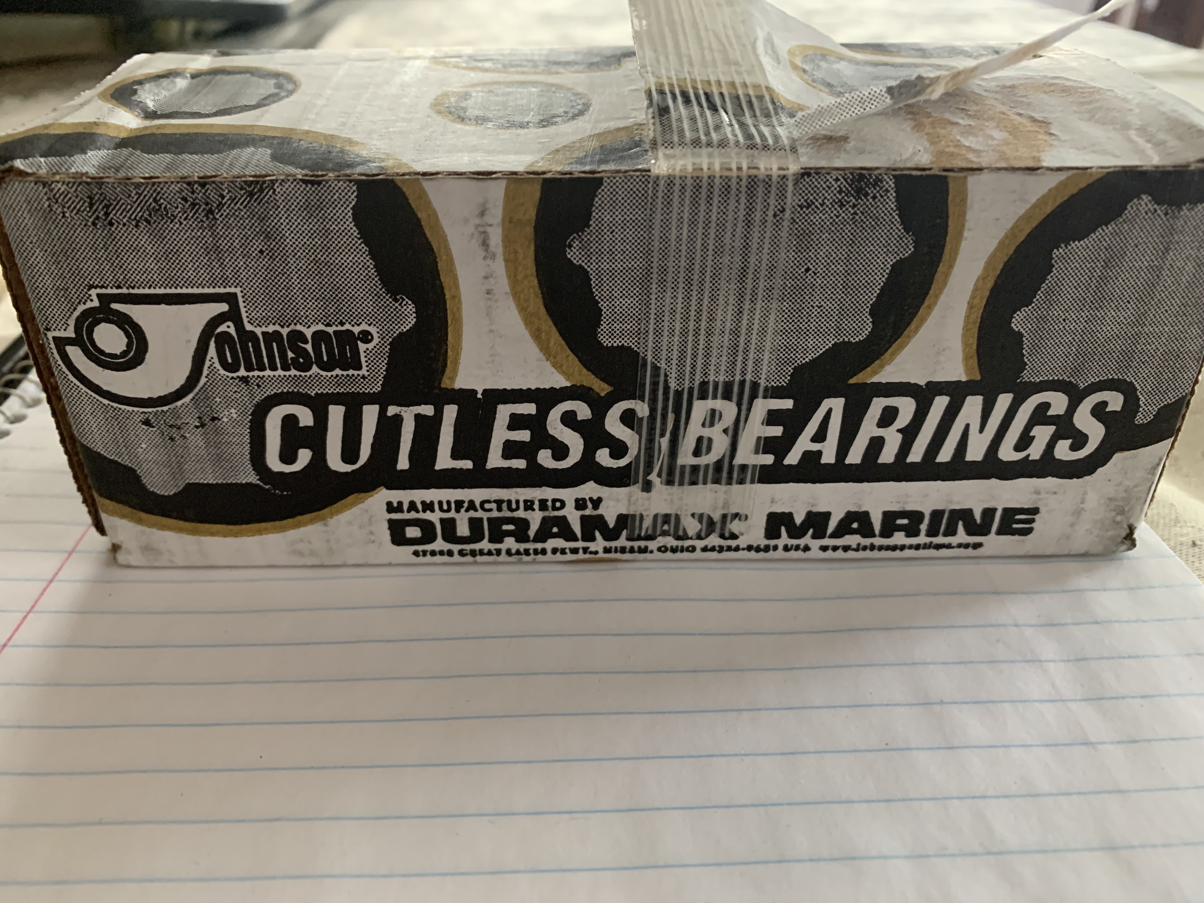
Reading several blogs and email threads, I was lead to believe that finding a cutlass bearing would be a challenge. It was a surprise to find a new cutlass bearing available from HR Parts several weeks ago. I bought it without hestitation.
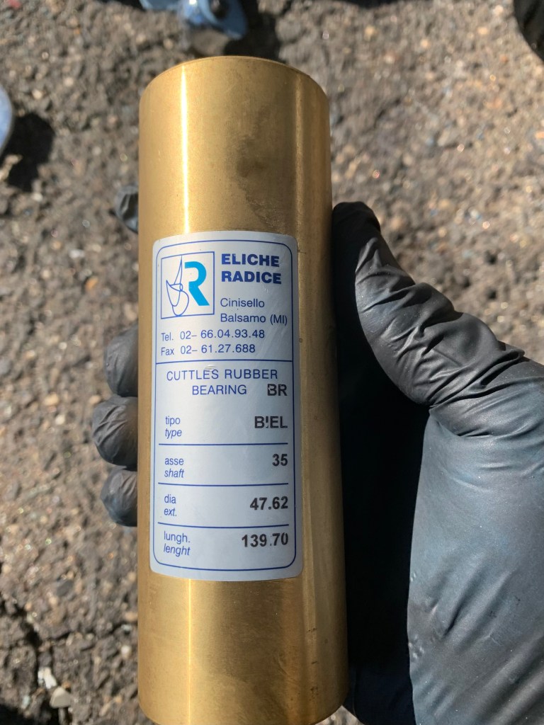
The wrong size!
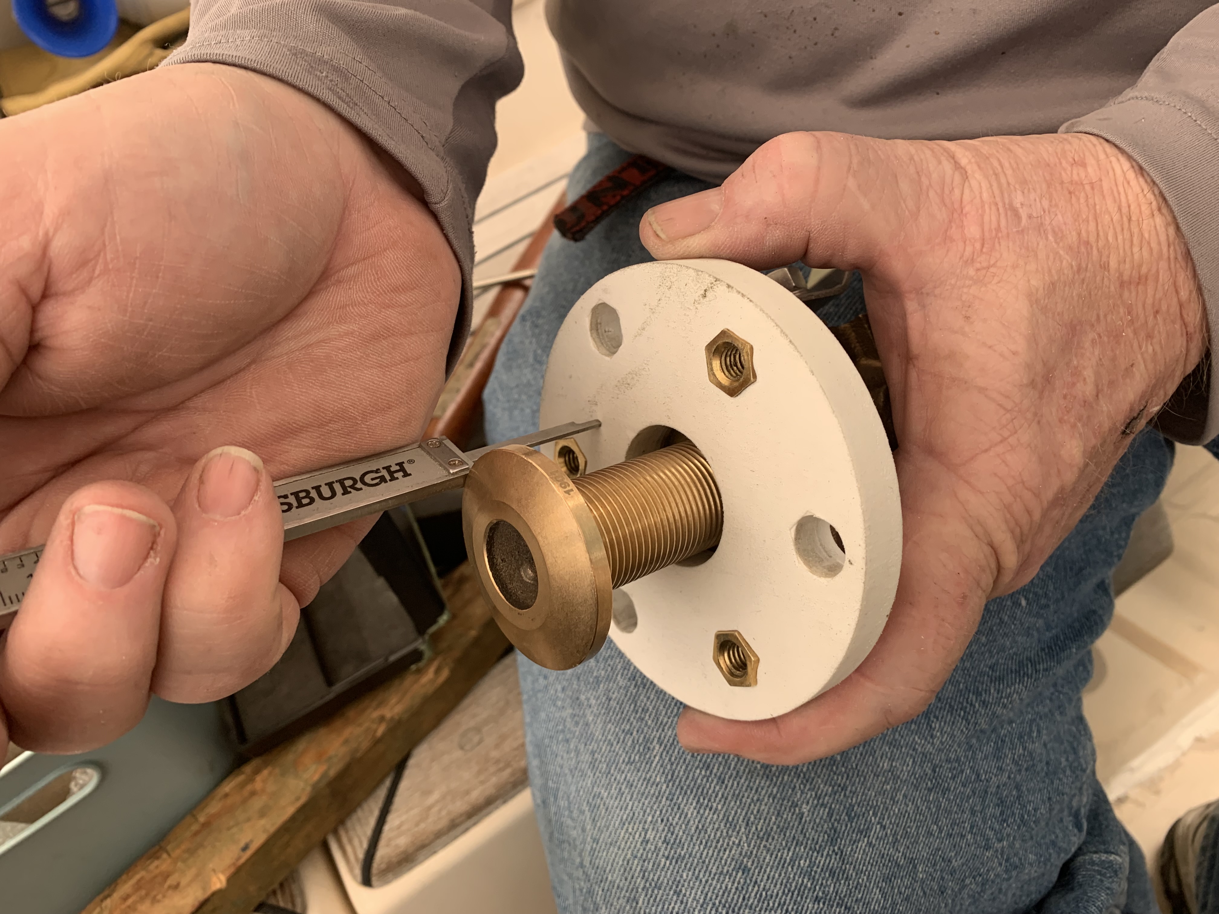
Once the old cutlass bearing was removed, I was excited to install this new bearing. I froze it very cold in our freezer and also heated up the housing to ease installation. The bronze housing heats up quickly even with indirect heat on a cold day. Not knowing what I would be dealing with, I broke open the plastic bag that it came in and tried to insert it by hand. It went right in, no problem! The problem is that it was 1-2 mm in diameter too small, so even after equalizing temperatures, the bearing was too small.
I finally did what I should have done originally; that is, measure the internal diameter of the housing. It was 49-50mm. so I found a cutlass bearing made domestically for a 35 mm shaft, 50 mm diameter by Duramax Marine. Once the old one was out and the internals were vacuumed clean, it was time to install the bearing. Once again, I froze the bearing and heated the housing. I had to really stuggle to install this, because even after being frozen for days, the diameter of the bearing only shrank by 0.5 mm (down to 49.5 mm).
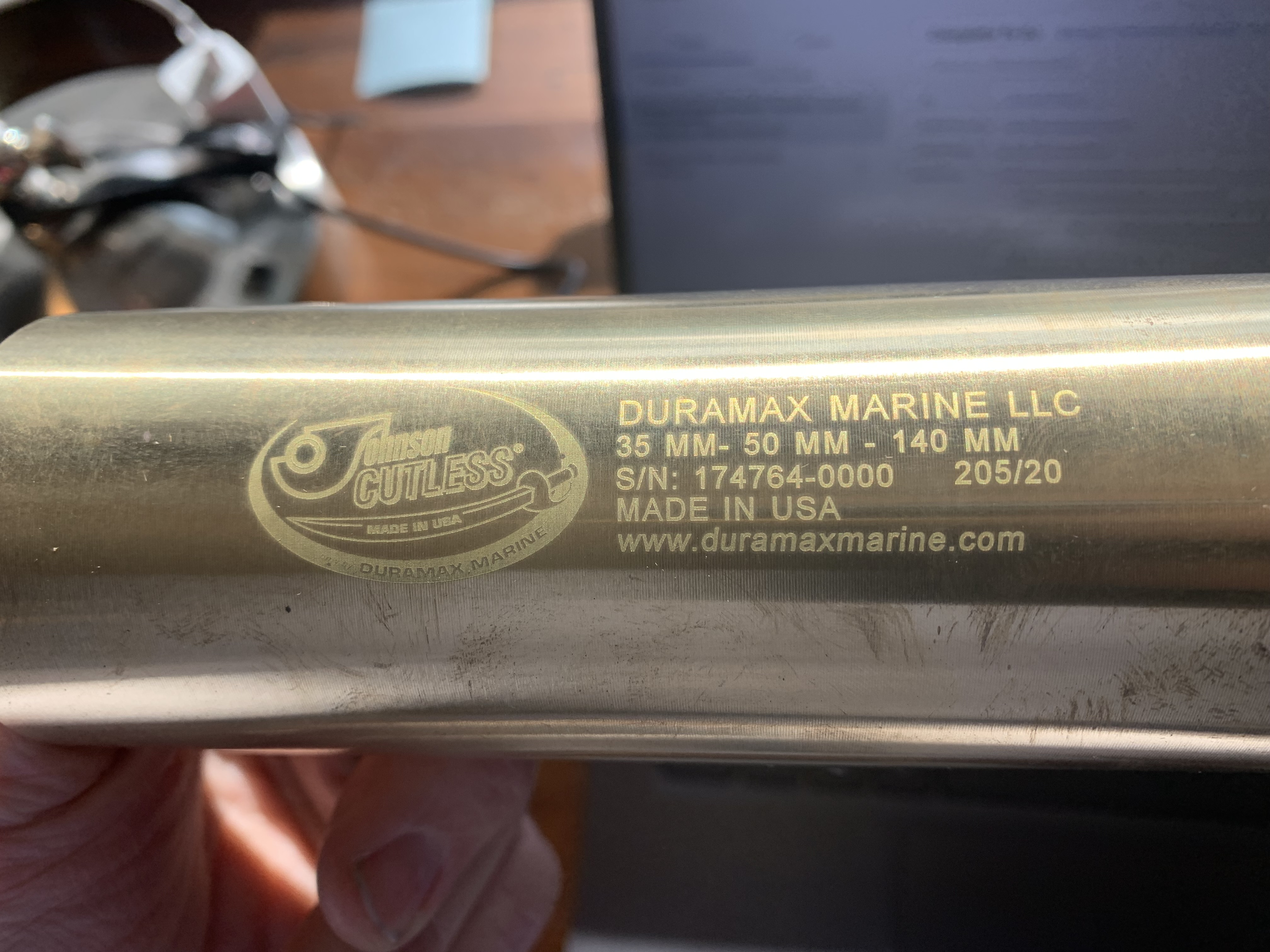
Getting the new cutlass bearing installed took a wood block and a 10 lb sledge hammer. There must be a better way to do this.
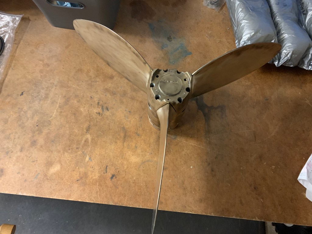
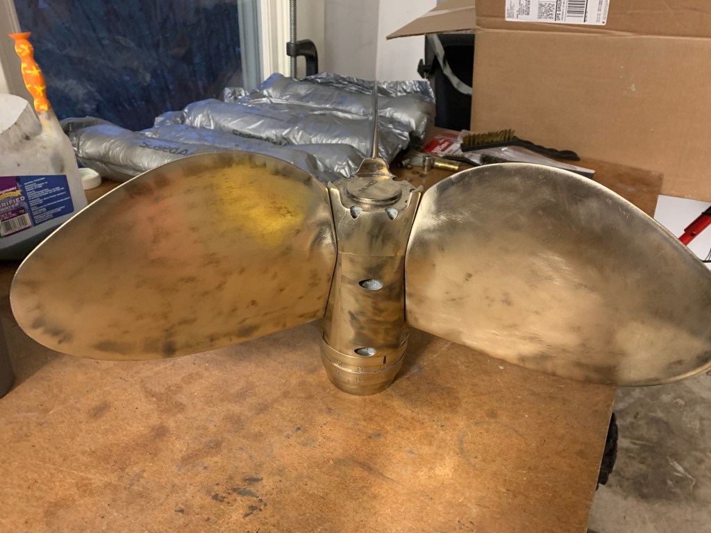
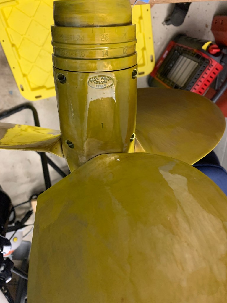
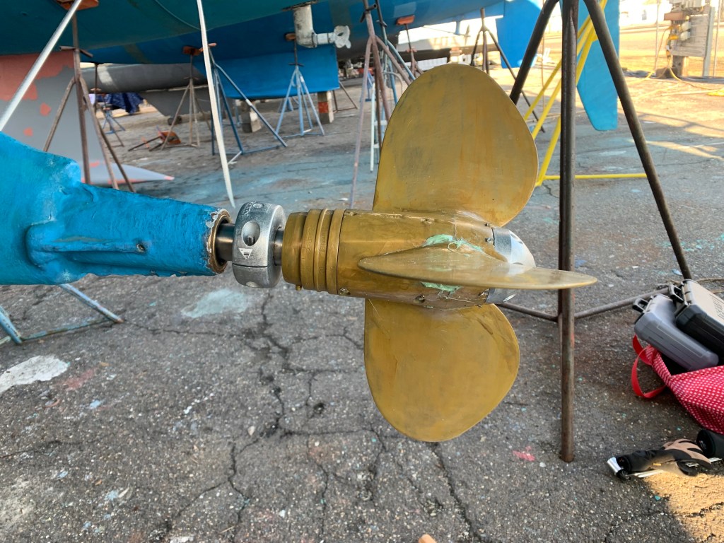
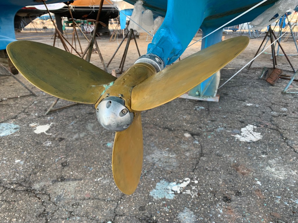
Install the propeller – Recall that I applied PropSpeed on the bench a few weeks ago, and so now we are ready to install the propeller. First we cleaned up the propeller shaft with a wire wheel on a 18V Milwaukee drill. I really like my Milwaukee power tools by the way. The prop shaft is too long to come out of the boat as it hits the skeg. I don’t take the time to investigate this further; perhaps it is possible.

One very important detail is that the threads on the propeller shaft had some minor damage on them. I purchased several dies in an attempt to fix the threads on the shaft, and I measured the teeth to be 2.0. I didn’t know which die to use, but most HR owners and even the MaxProp representative told me that M24x2 would be correct. Taps and dies are still not part of my knowledge base even after all these years doing all sorts of mechanical jobs. It seemed to me that M24x2 was 1 or 2 millimeters too small in internal diameter, because when I tried to thread it onto the propeller shaft, it would only go on a few threads. I was tired and didn’t have time to sort this out, but I can say that using this die (even if incorrect size) did the job to repair the threads. By the way, MaxProp has outstanding customer support at PYI.
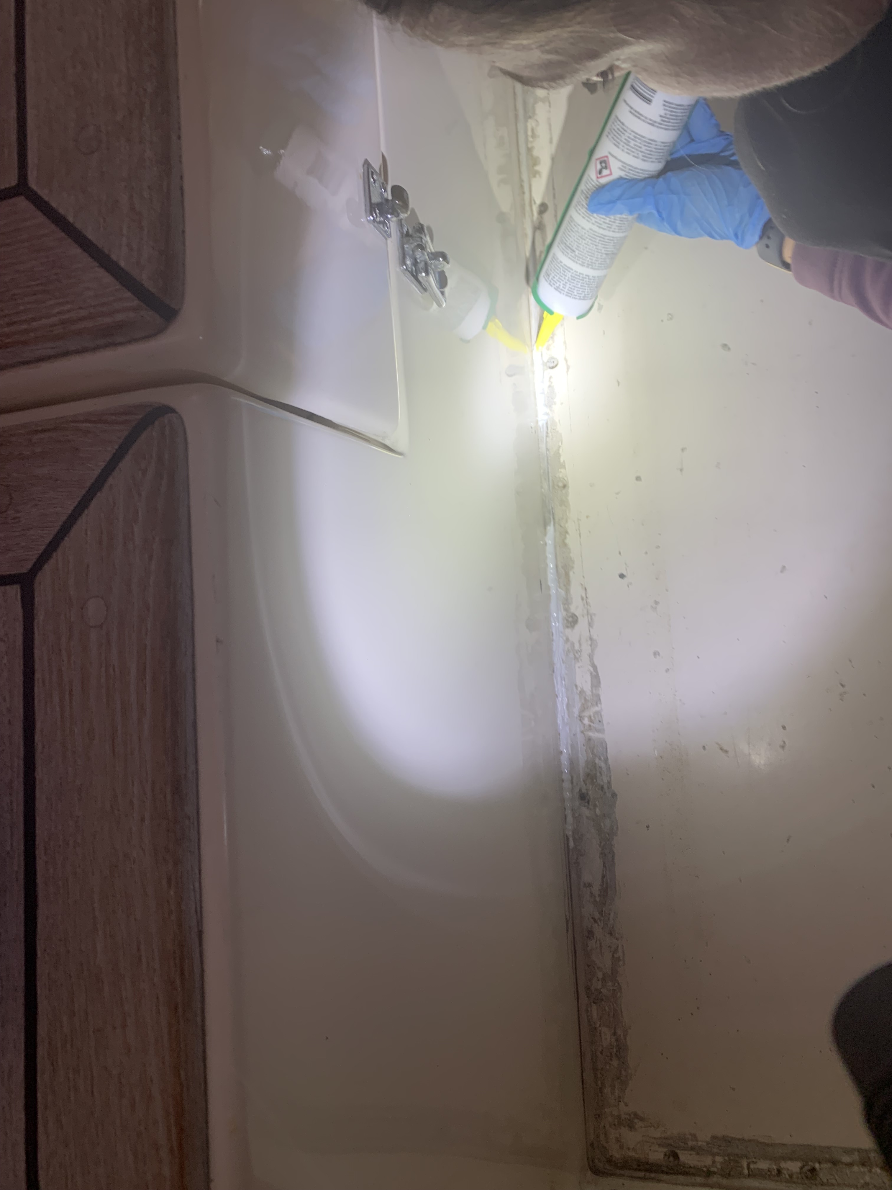
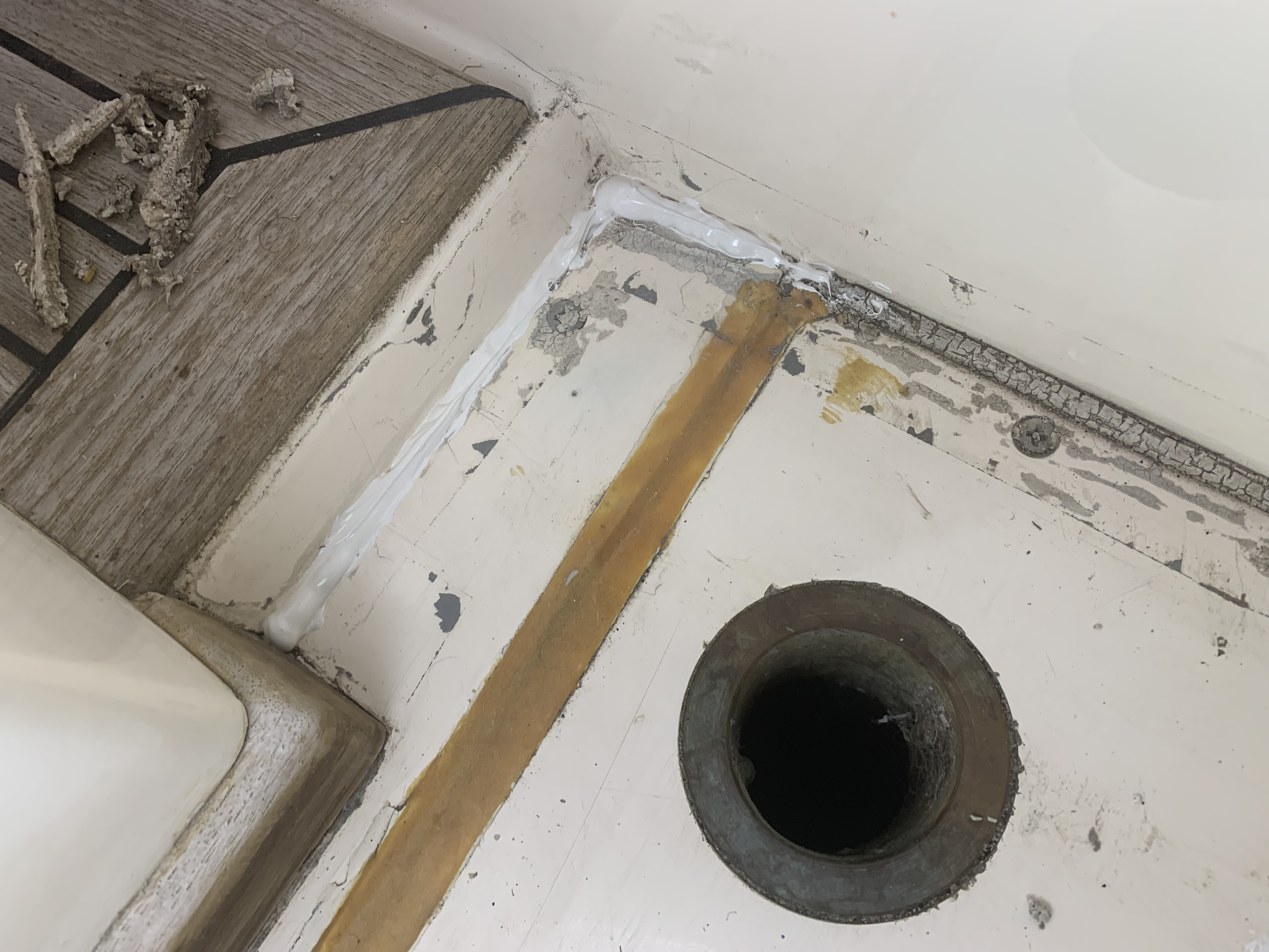
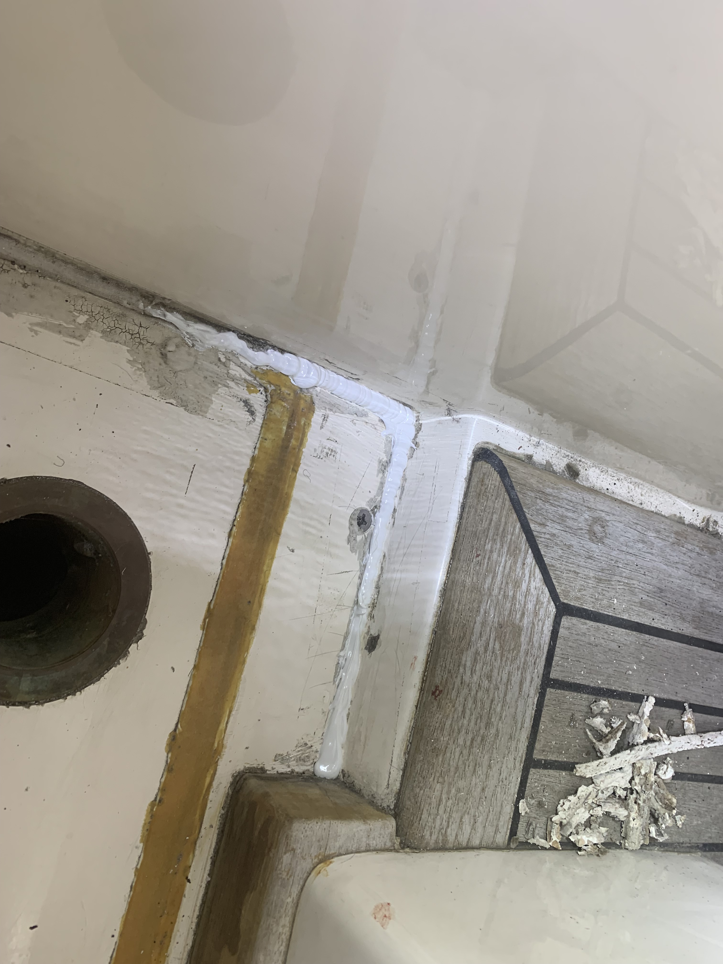
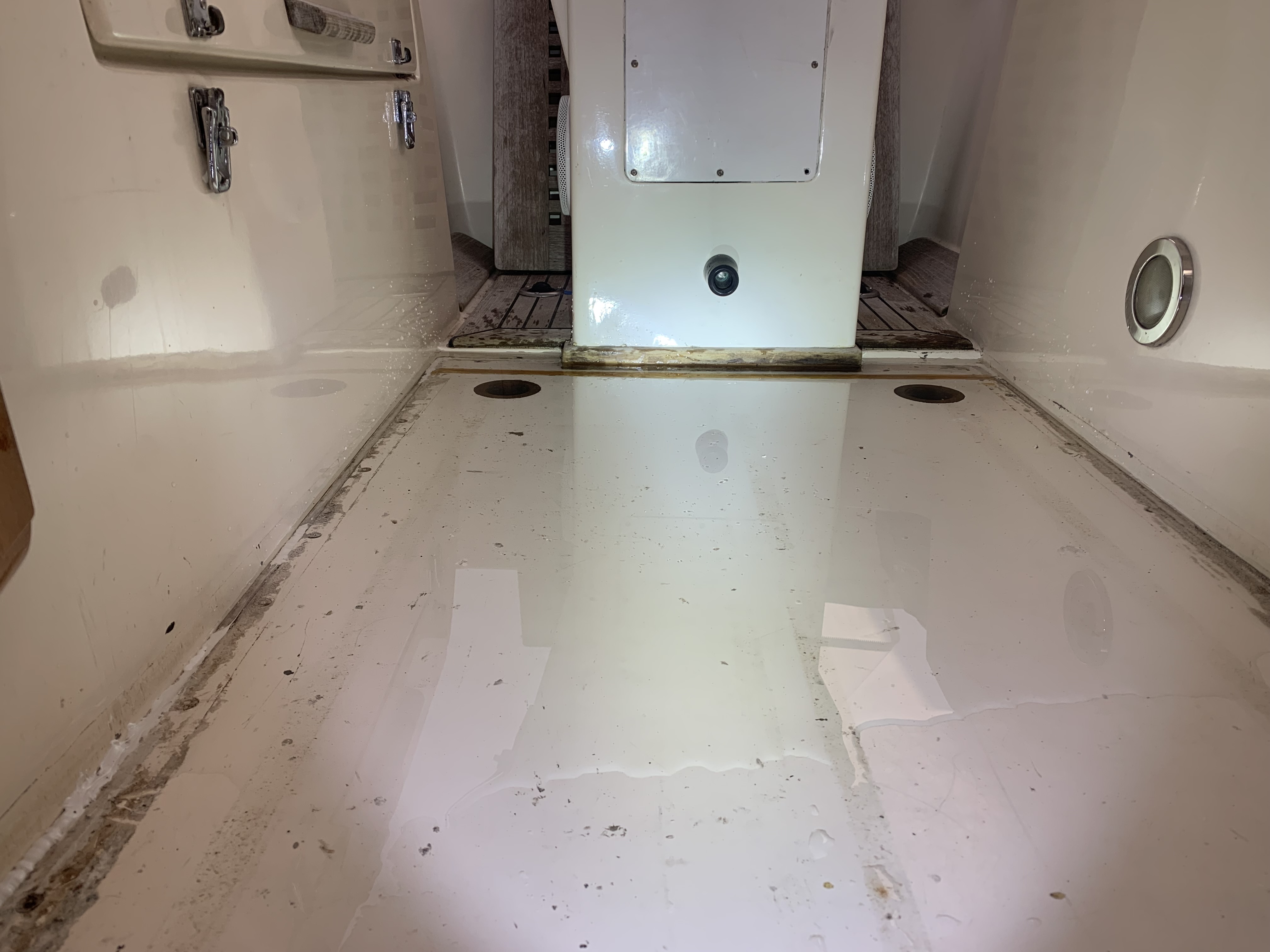
Pressure test of the cockpit floor seal – we have a suspicion that the cockpit floor is leaking and would leak profusely in a rain storm…that the seal is bad. We need to test this out by closing both cockpit drain seacocks, filling up both cockpit drains and then filling up the cockpit floor with a few inches of water giving static head. Let’s see if this thing is leaking. If it is leaking, this will be a huge job to complete. If this is not leaking, then we will start installing the new Webastos immeidatley.

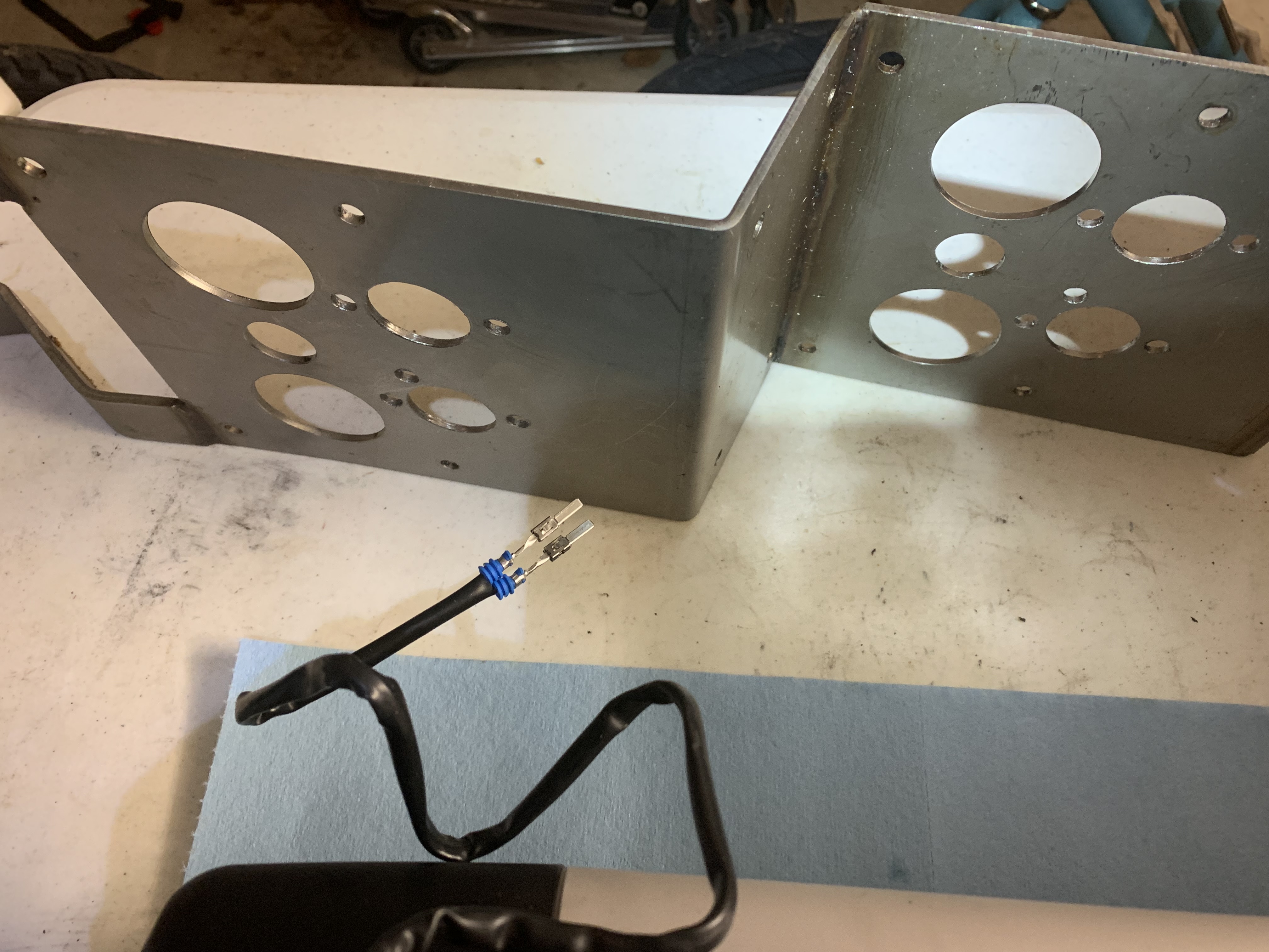
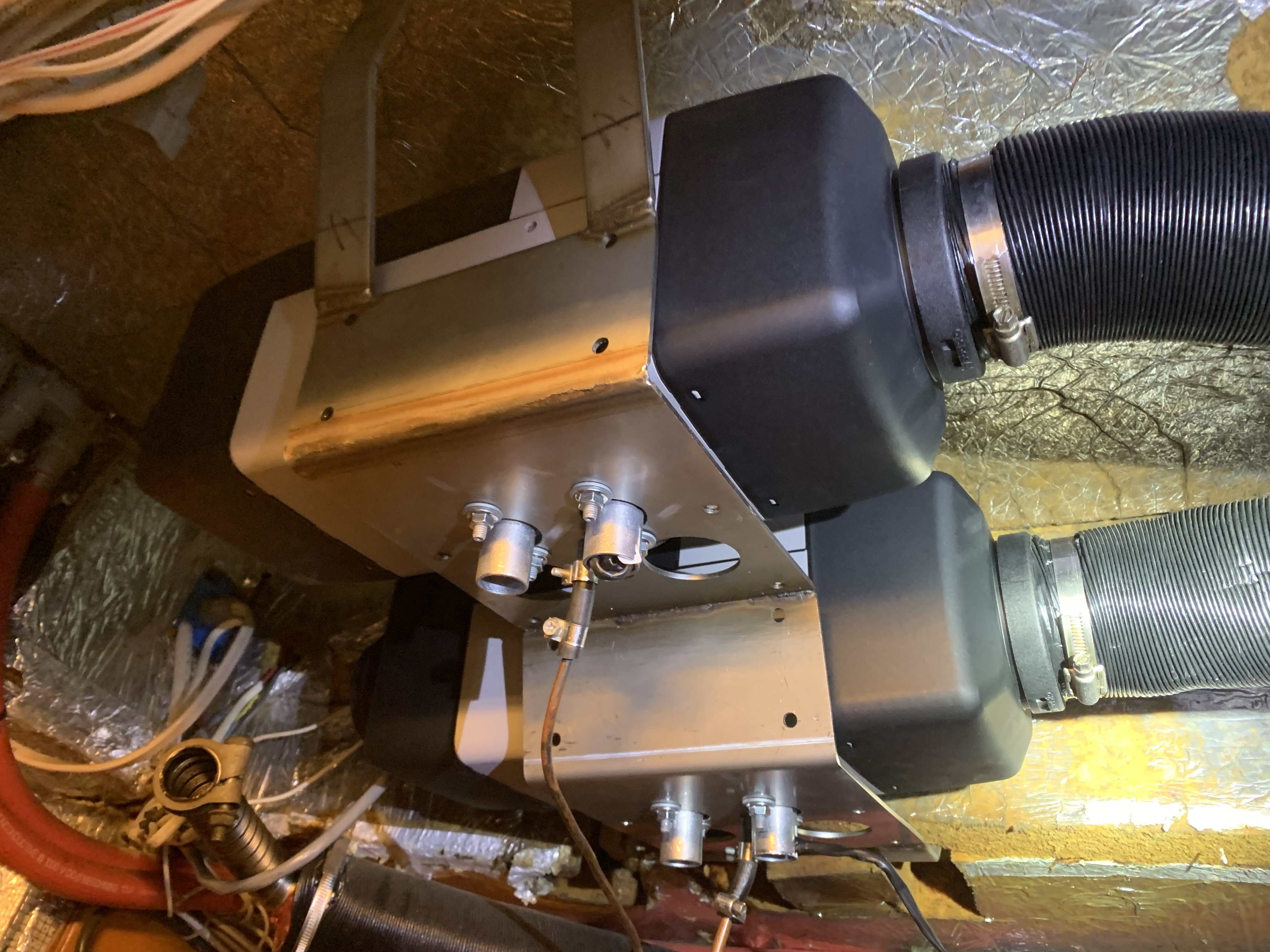
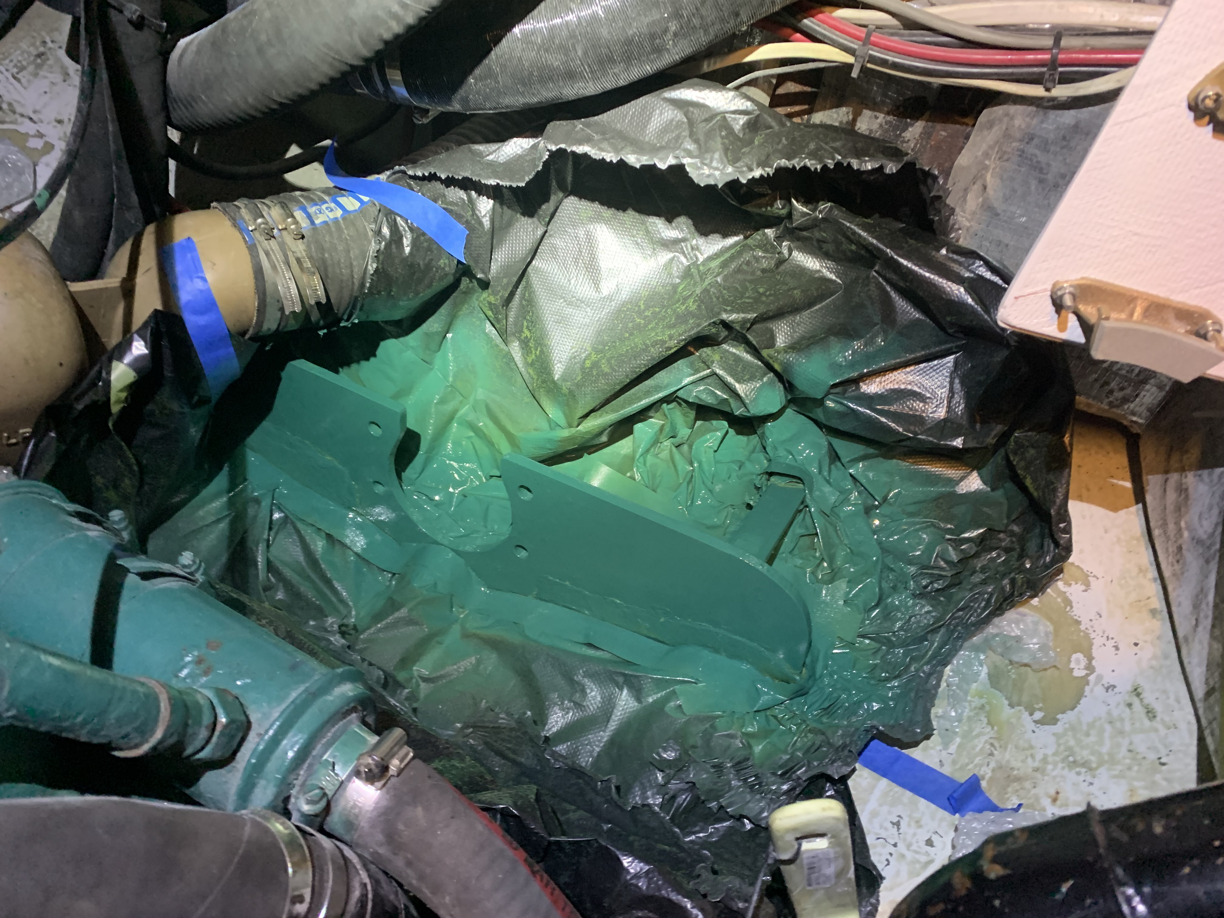
Install new Webastos – we re-used the original hanging shelf/bracket but made some modifications to accommodate new bolt patterns on the bottom of the EVO 40 heaters. I re-made the hot air supply muffler/silencer, because the original one was fragile at the ends and was basically destroyed during removal. I also purchased elbows for the combustion inlet/outlet. The outlet and elbows is 24 mm OD, and the elbow are perfectly designed to match this size. The inlet, however, is 25 mm OD, and so I had to modified the new elbows slightly to fit over the inlet. All of this is done and ready to install now. But we did have to finish our uninstallation of our HL32D control interfaces at the panel and the wiring loom. We started to remove the original wiring loom, which is highlighting a few general wiring observations that we will document and work on. I will have more detailed pictures of the Webasto installation in future posts.
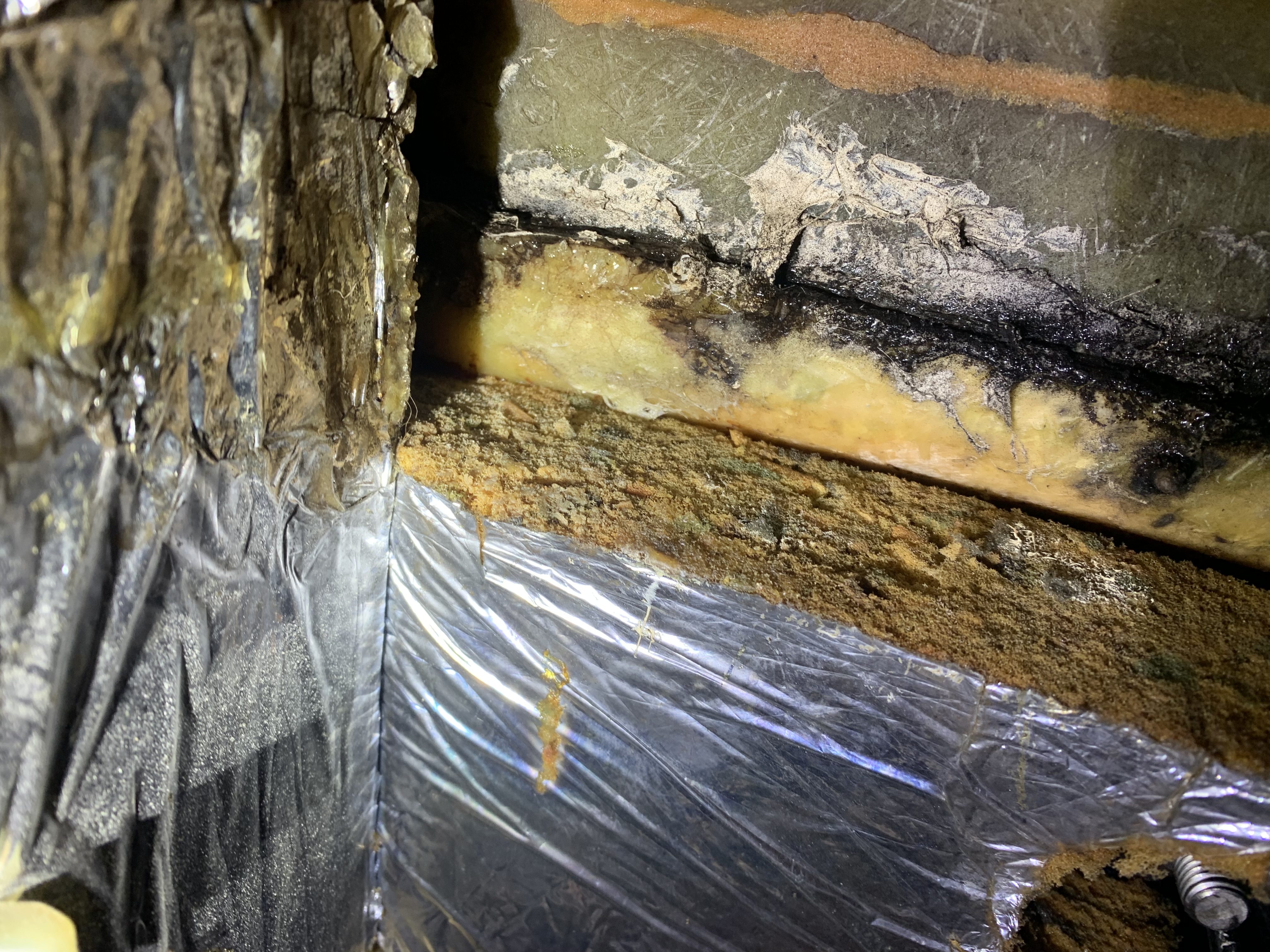
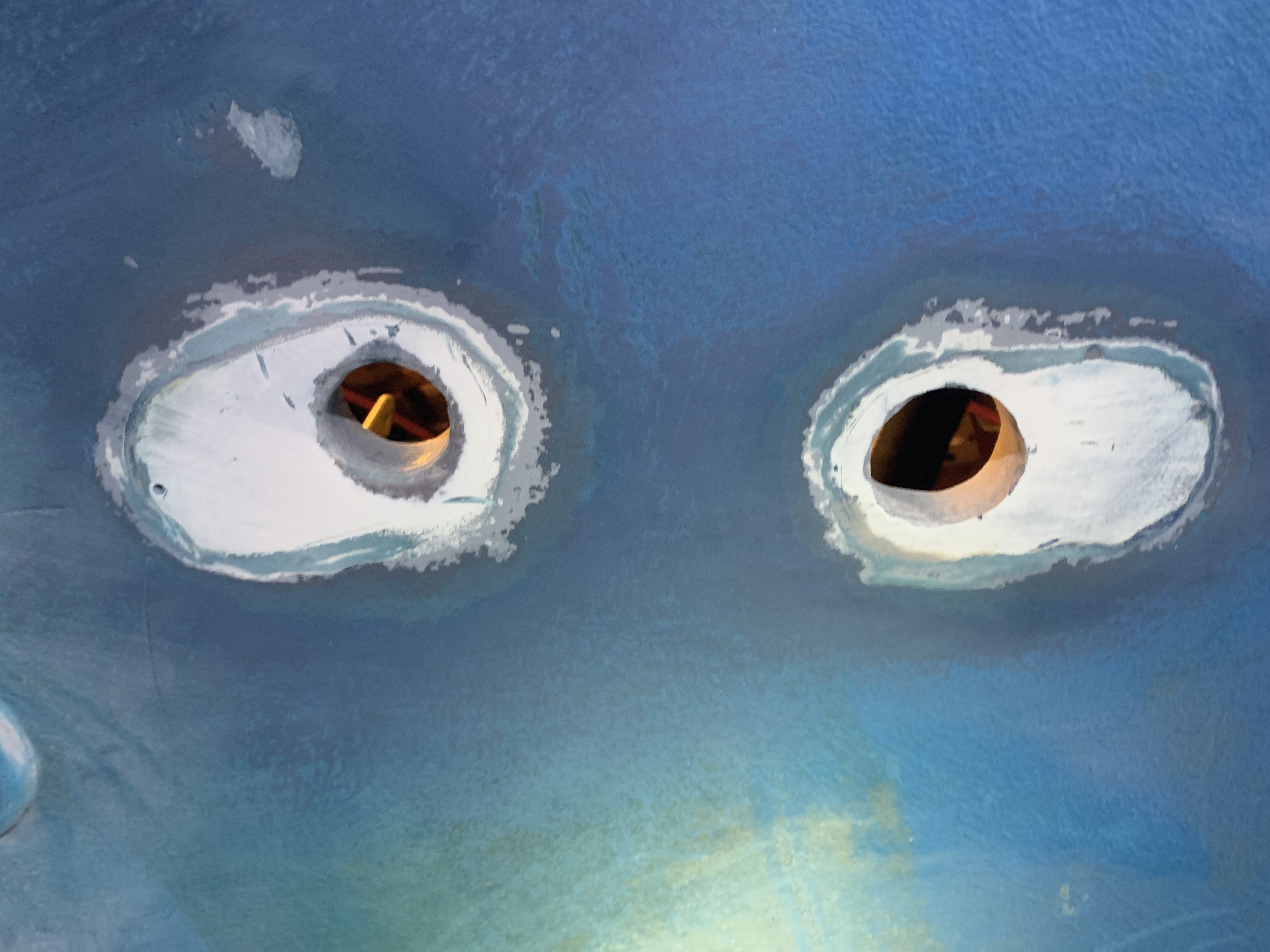
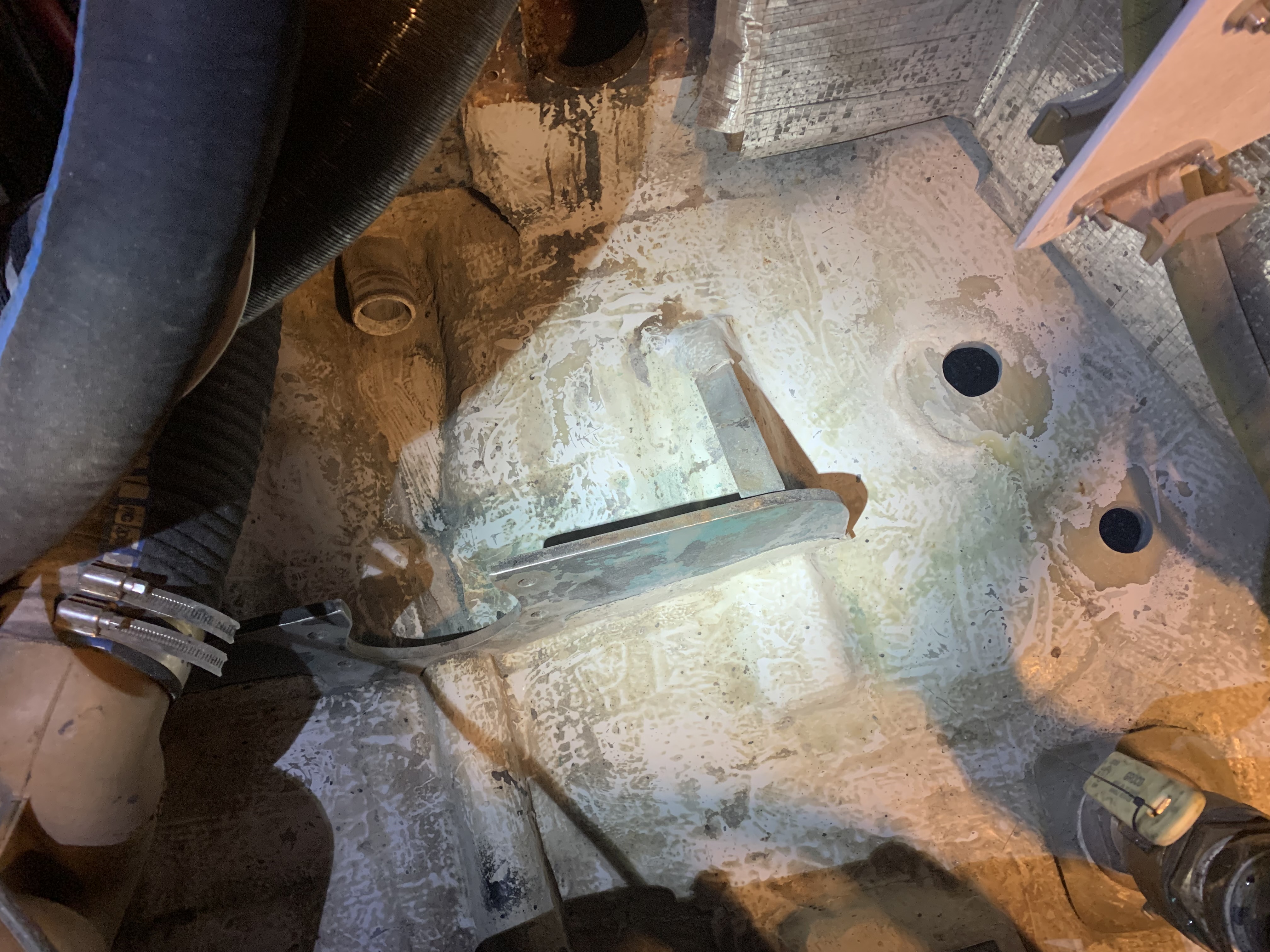
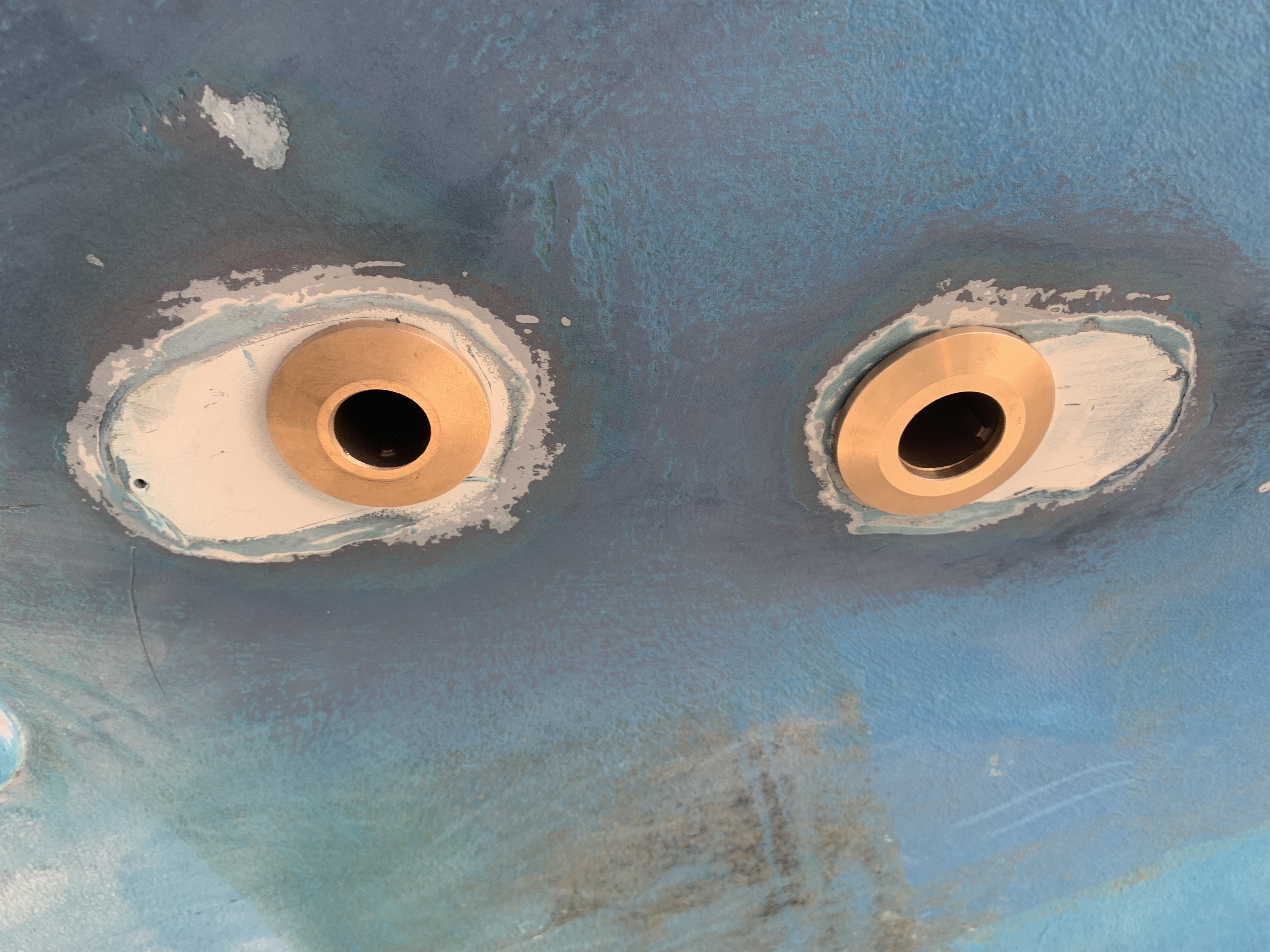
Replace thruhulls – We replaced 4 thruhulls with new Groco thruhulls using the Groco backing plates. In this process, I re-arranged and organized the thruhulls to minimize hoses traversing the engine bay and simplify the entire design. I started by cutting out the thruhulls and hull-side strainers with a 4″ grinder and other tools. Then I took a knurled grinder attachment for my drill and removed any remaining original caulk from the outside. I then used a hammer and masonry-style chisel to break out the original wood backing plates. I followed all of this up with 80 grit dry sanding using a Porter Cable square sander.

Ray drove up from MD to help me with the thruhull installation. We started by measuring the length of all of the thruhulls to ensure we had acceptable depth and penetration of threads up into the thruhull valve. I am using all Groco products here. We had to shave down one or two of the thruhulls to length as the goal is to thread almost all the way up to the ball of the valve. We measured the hull at the aft end of the engine to be around 0.75″ thick.
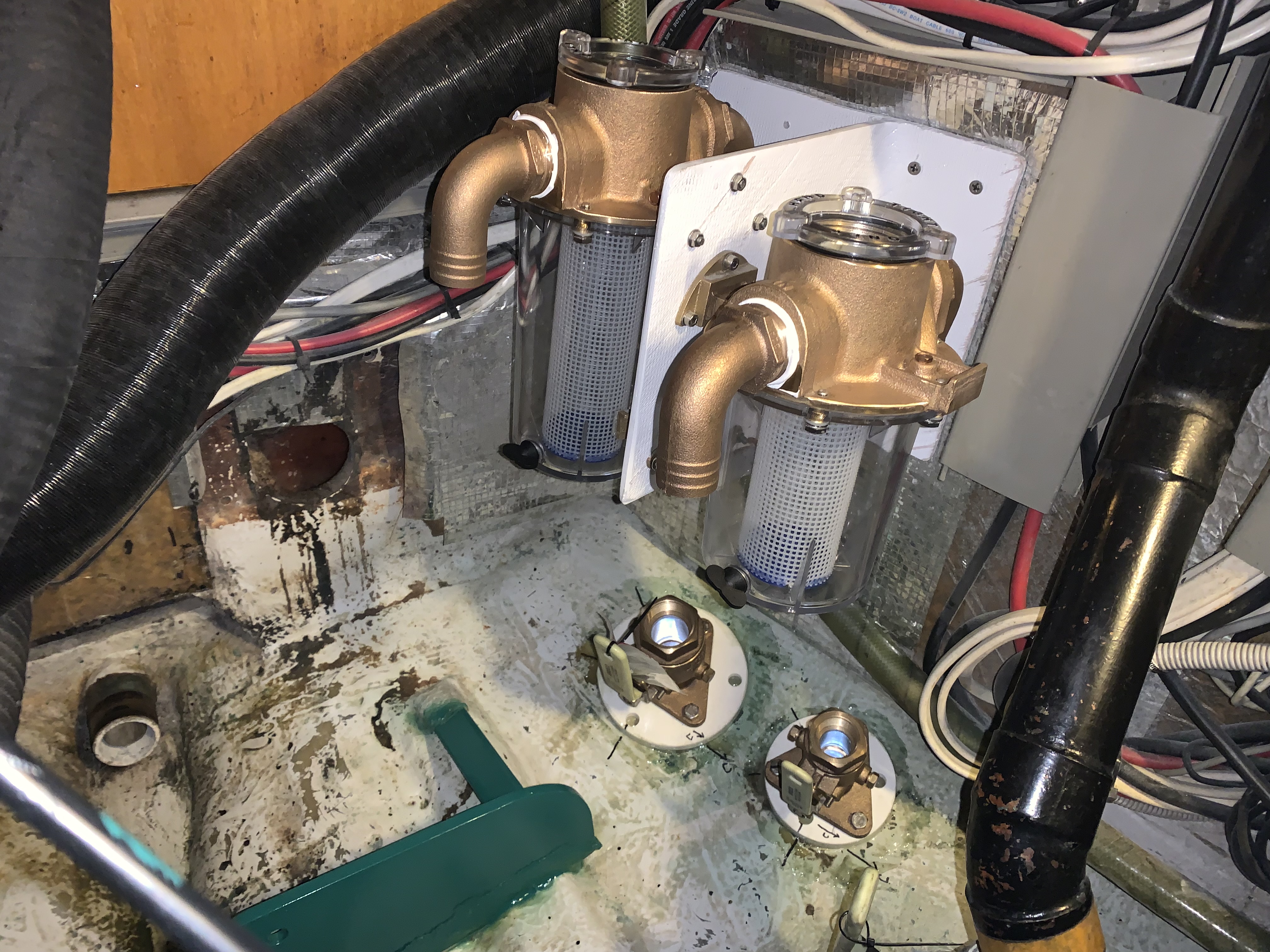
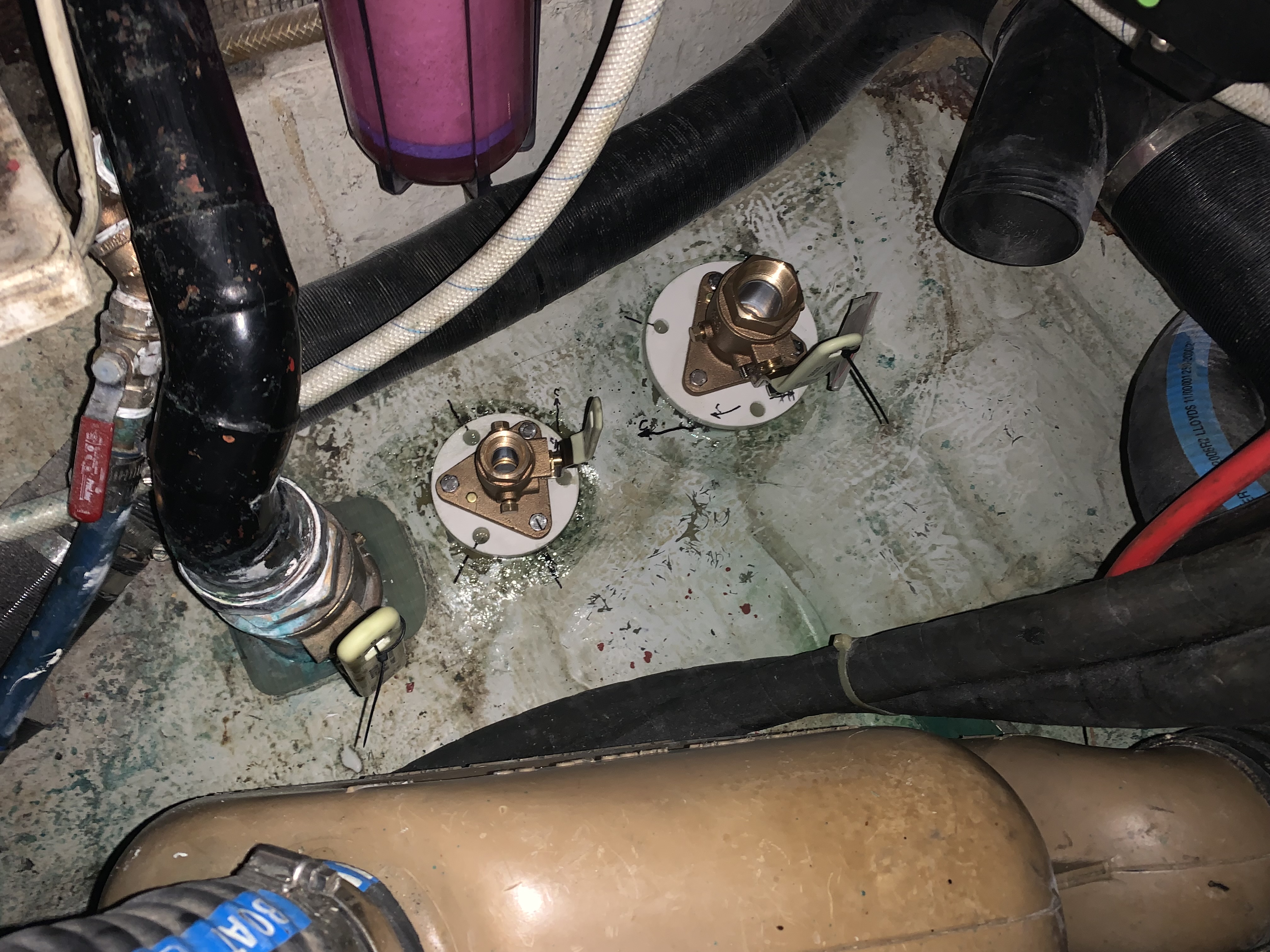


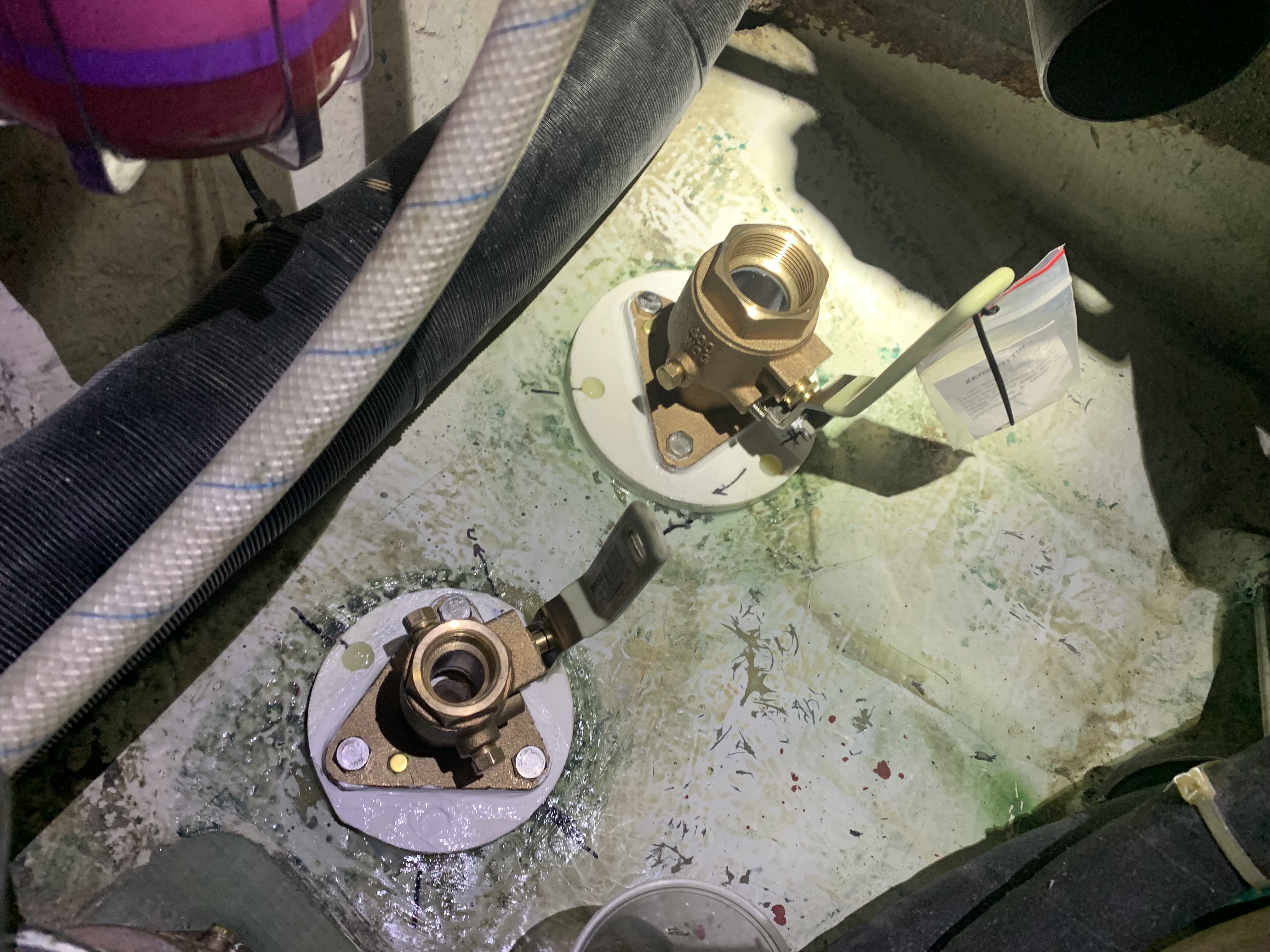
We dry fit all of the pieces onto the hull, then I was able to specify and mark where I wanted the handles to turn into the engine room. I made alignment marks with a Sharpie on the backing plate and the inside of the hull. I wanted all of the thruhull valves to be able to be opened and closed without interfering with other valves and hoses. After we did all of that, we sprayed the thruhull components with WD-40, because we didn’t have release wax. We then put six10 expoxy on the bottom of each backing plate, aligned it with the valve dry fit on top and the thruhull pulling from below. This secured the backing plate flush with the hull making an excellent seal. The next day, we pulled all of the threaded parts off, wiped them free from WD-40, rough sanded their surfaces, and then re-installed them with 4200. I’ll show more final pictures when complete.
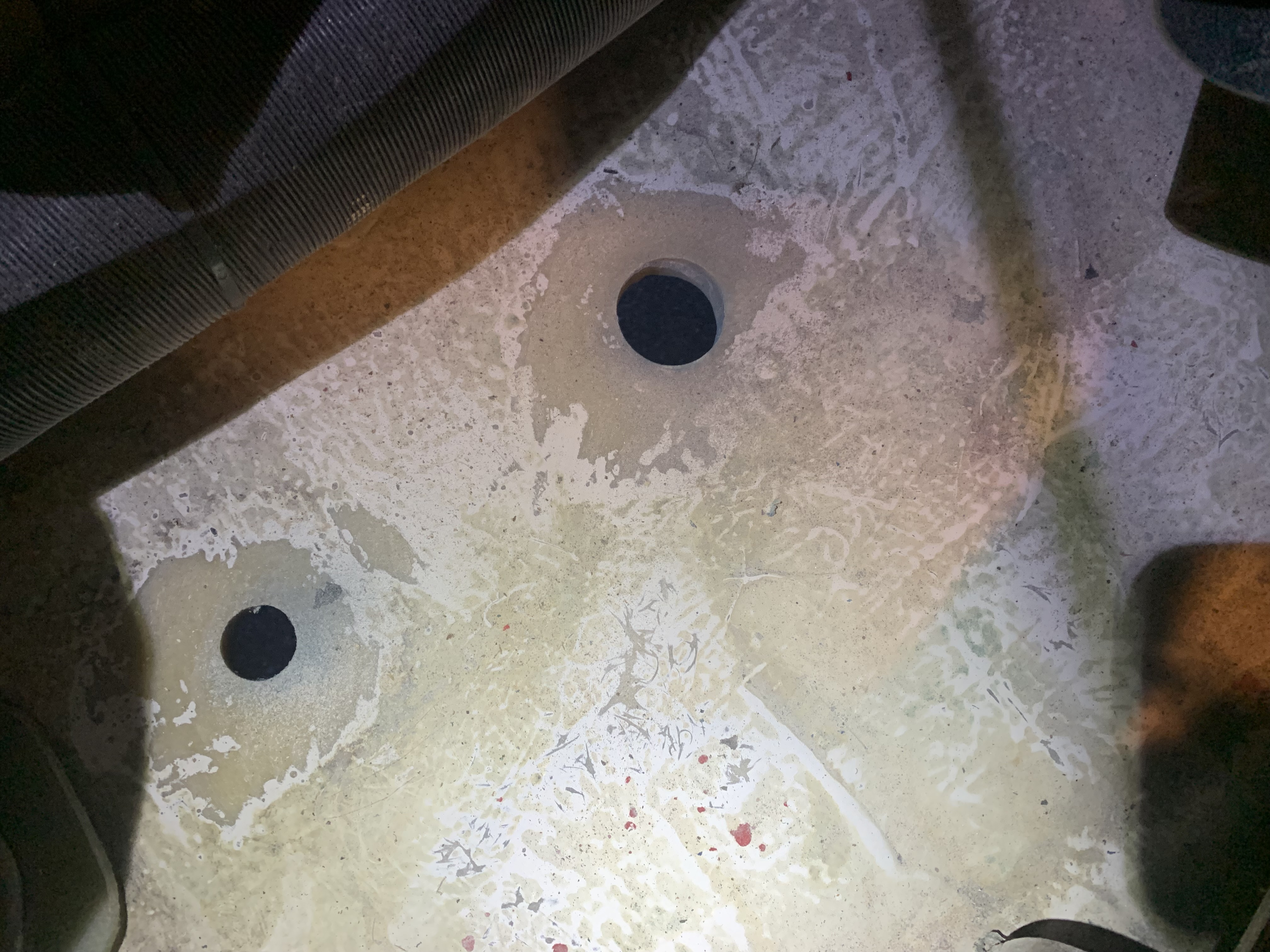
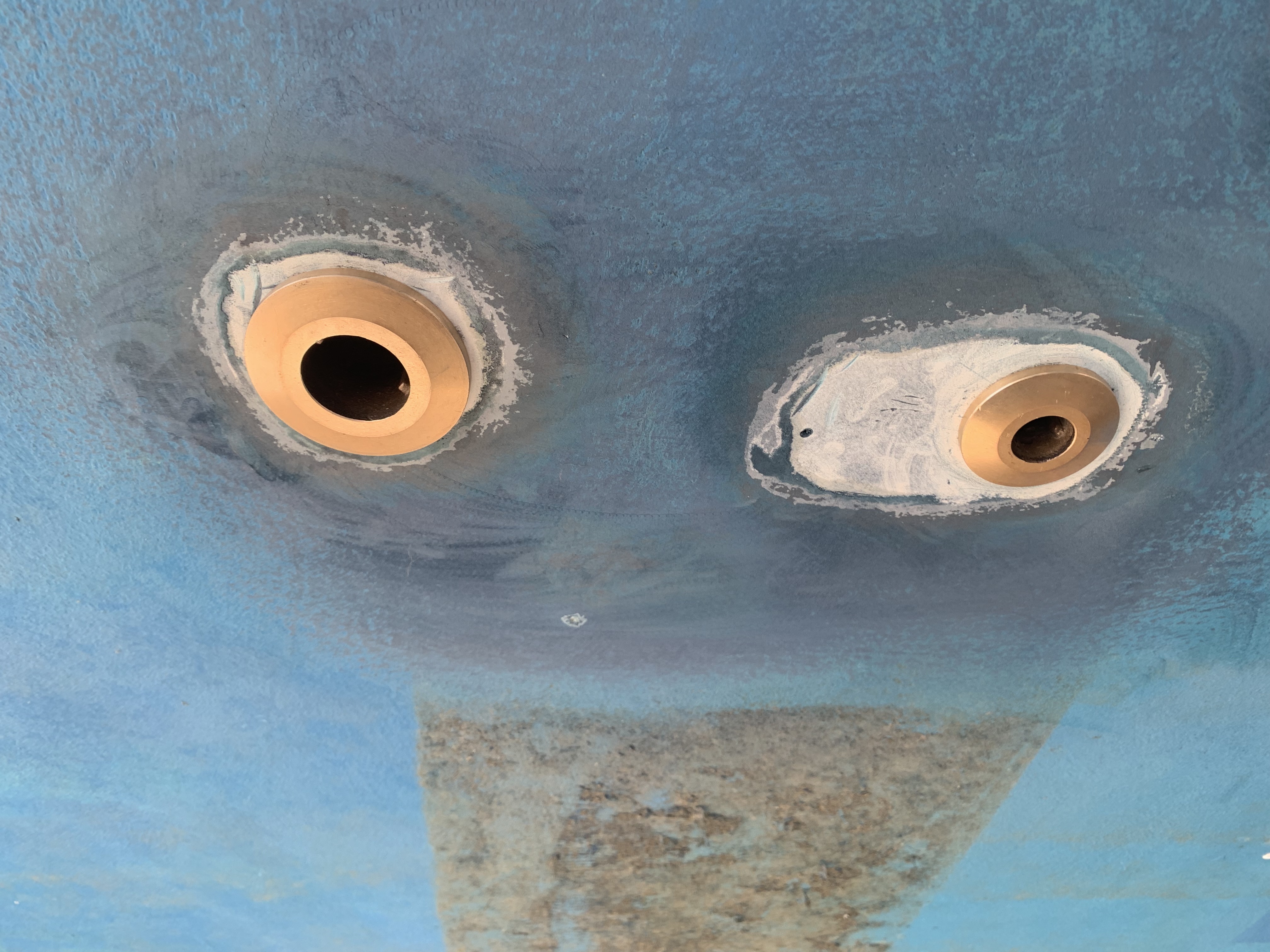
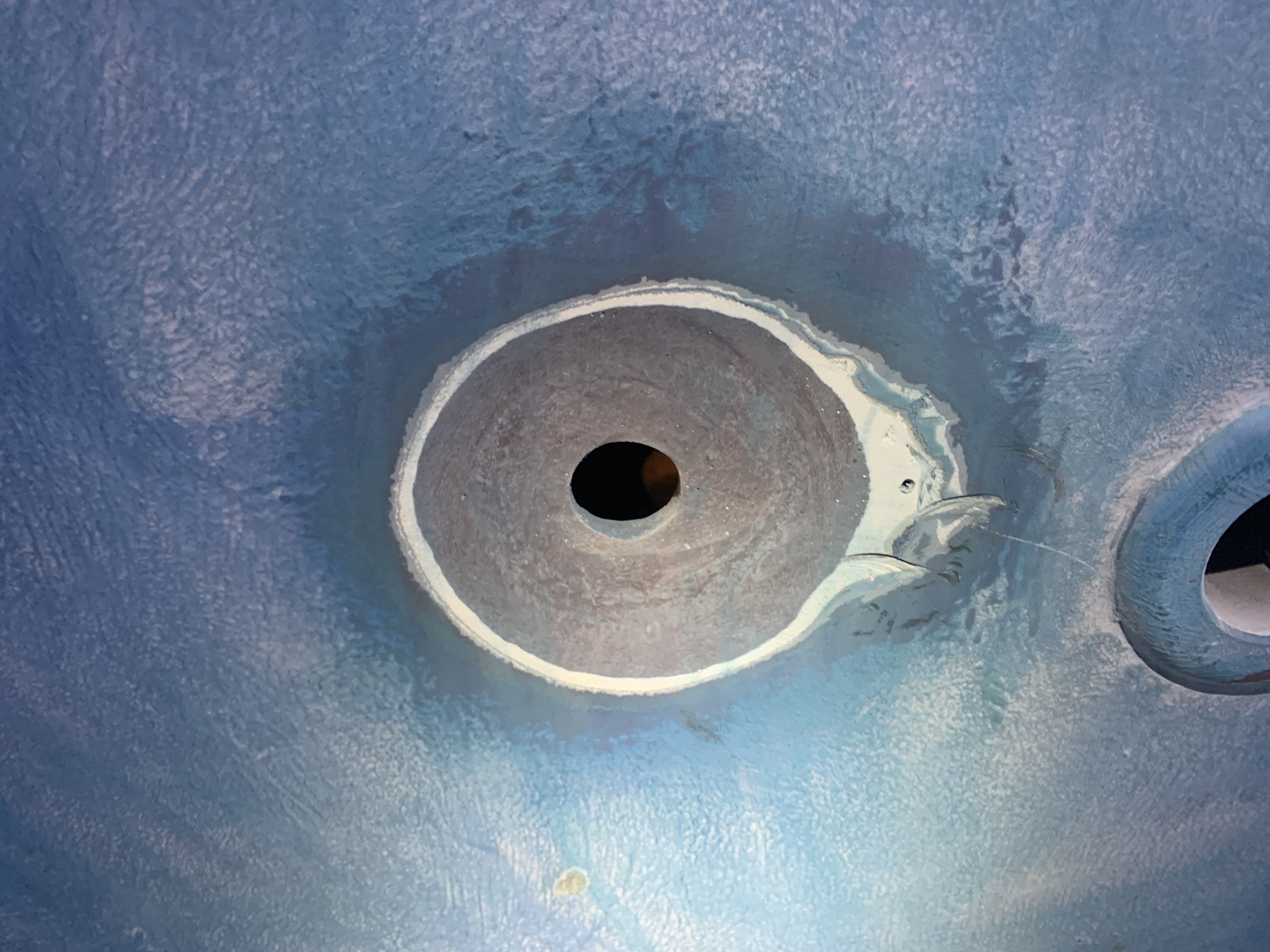
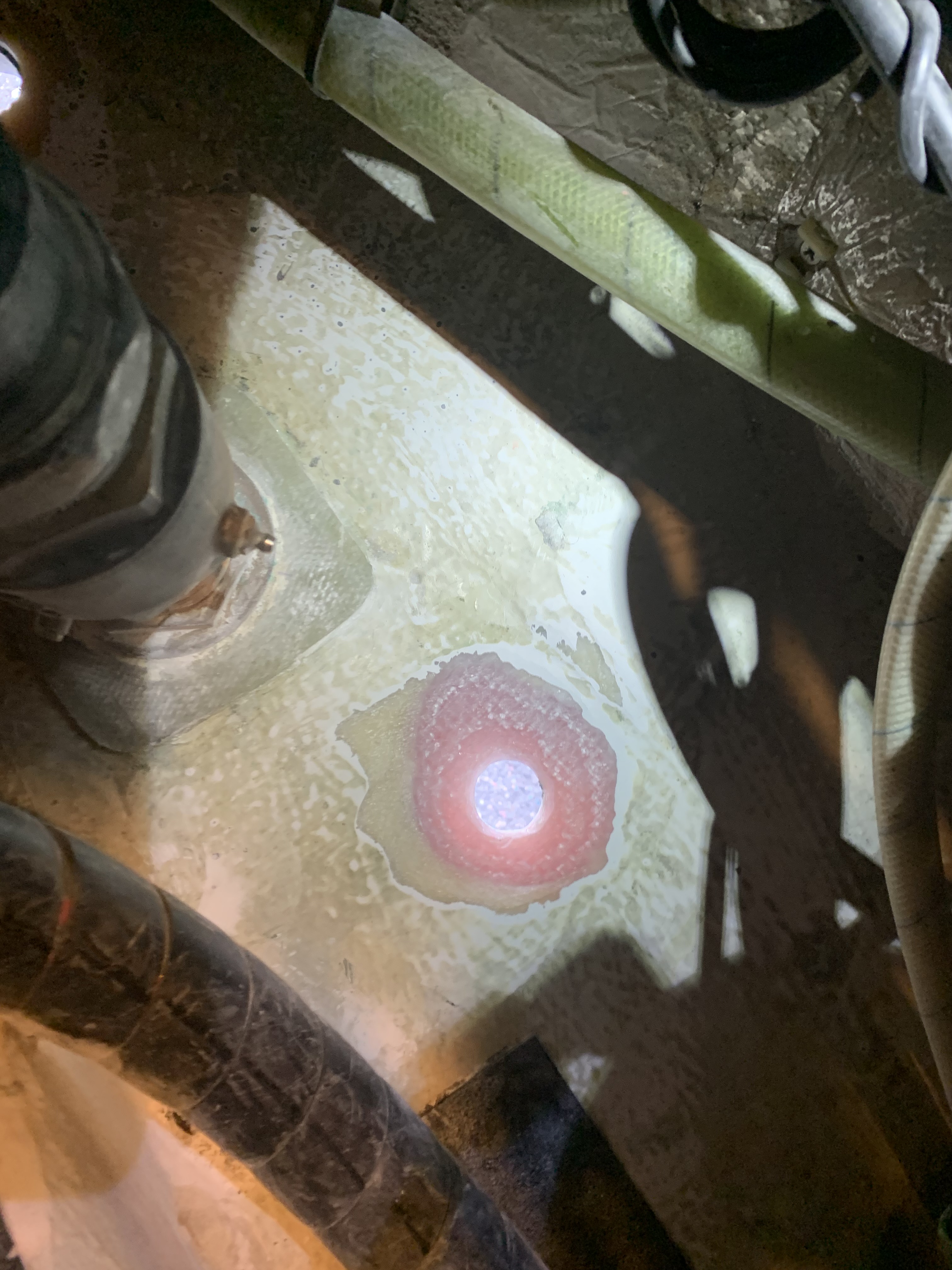
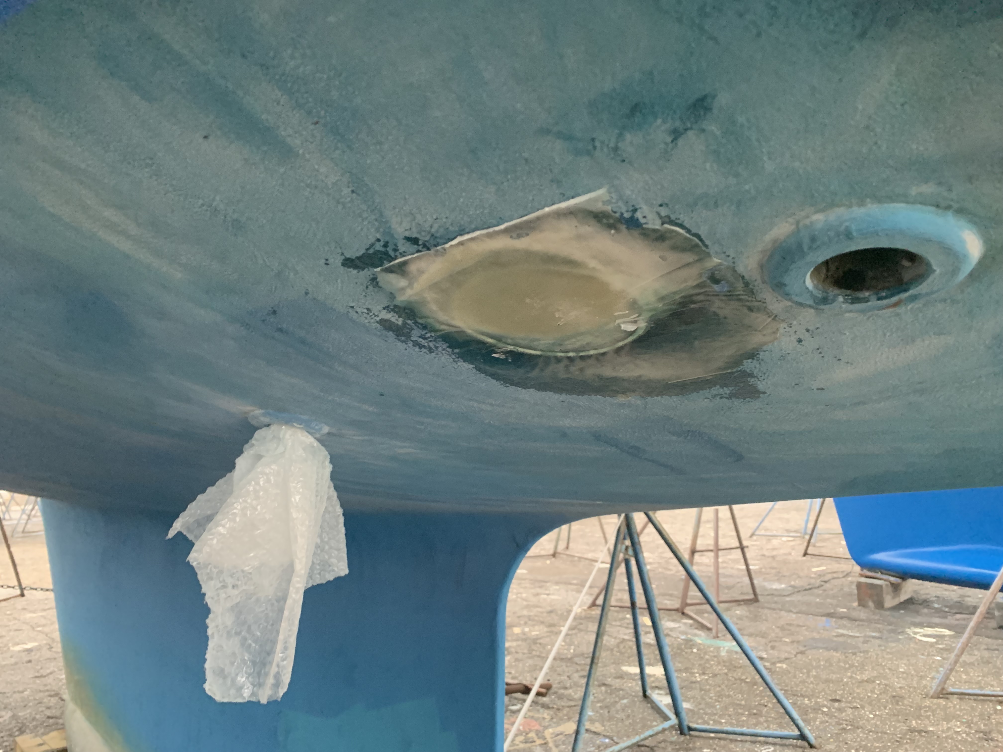
Eliminate a thruhull – I believe in having less holes in a boat as possible and practical. One of the previous owners or possibly at the Hallberg-Rassy factory, a 3/4″ thruhull was installed in the engine compartment to feed the watermaker system low pressure pump. Unfortunately, that thruhull with its integrally threaded strainer was exactly at the location where you would enter the engine compartment to perform maintenance, and it became a kneeling or stepping point for leverage. Of course, over time, this weakened the thruhull, and so it was time to retire this poorly-placed component. I engineered one of the new thruhulls to be able to supply water to the watermaker, the refridgerator compressor for cooling and the deckwash with plenty of flow.
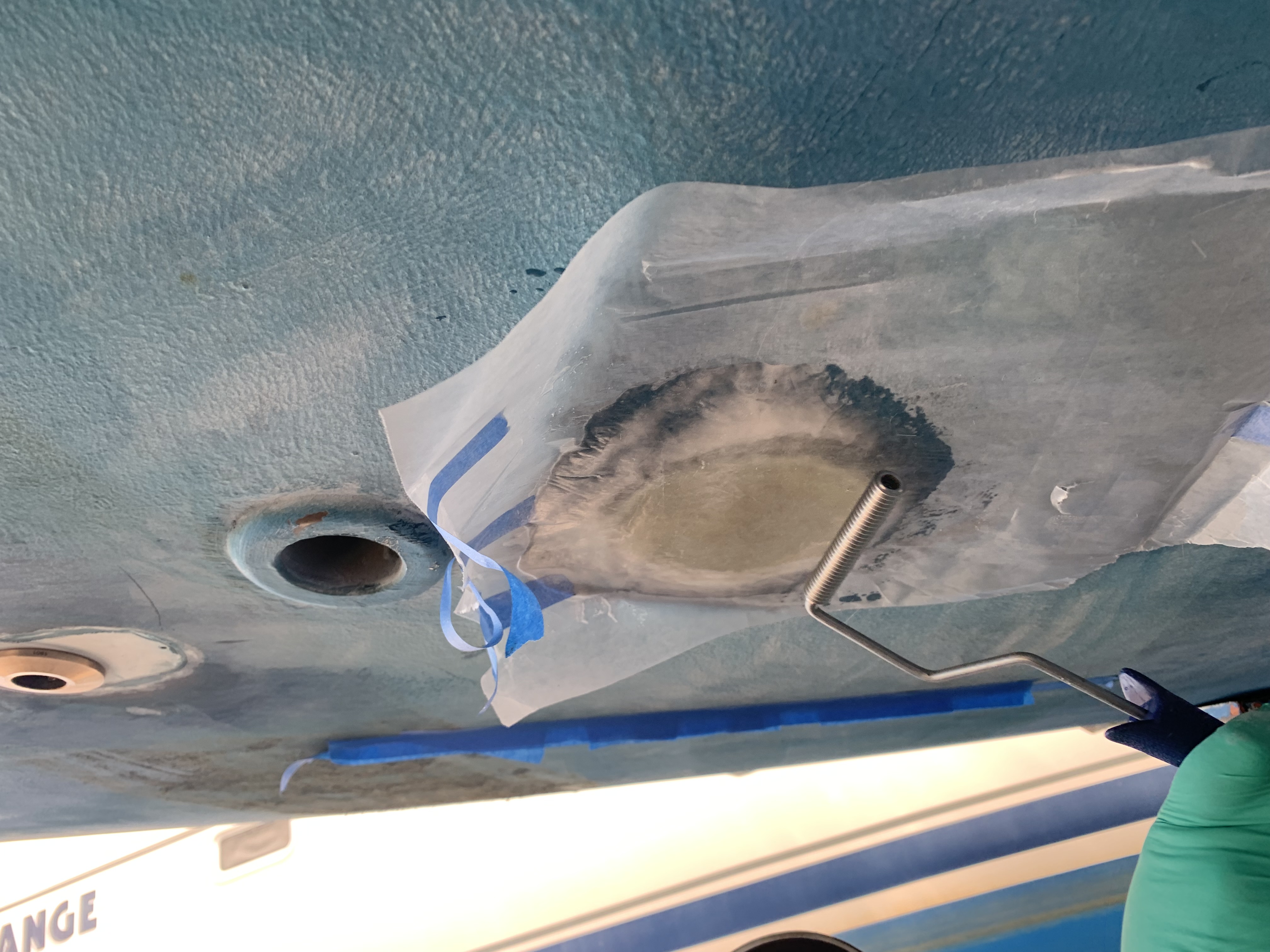
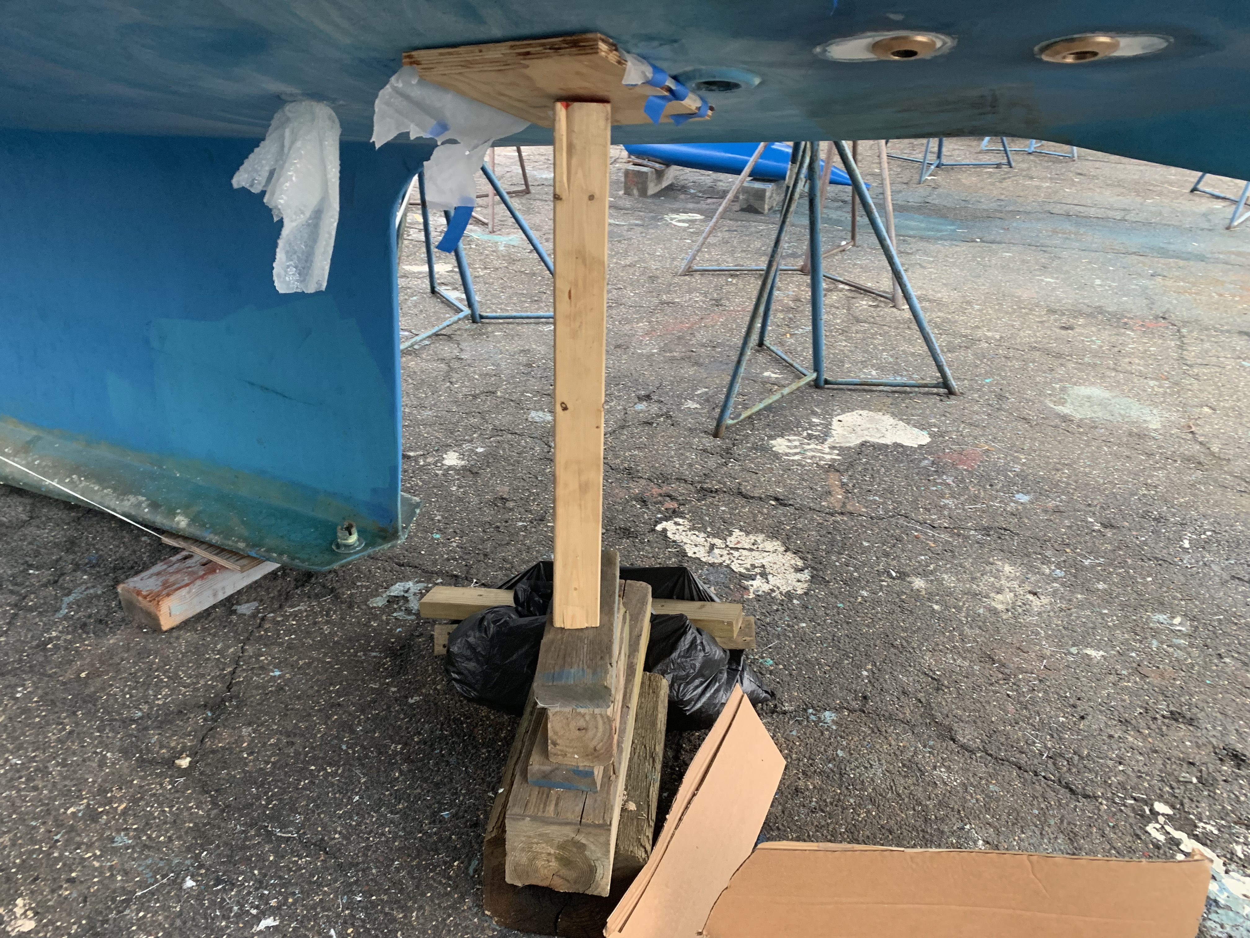
I cut back the hole on a 10:1 ratio with a 60-grit flapper wheel on a 4″ grinder. That was very quick and easy to do, but very dusty. This was done on the inside and outside. After cleanup, we sandwiched around 10-12 layers of fiberglass (mostly chopped strand with a few layers of woven) with West System epoxy and used thickened epoxy to coat the hull and also the hull-side layer. This was laid onto a piece of wax paper and then carefully secured up to the hull. We gave the outside of the wax paper a few rolls to compress the layers. We built the layers in situ on the inside of the hull, overlaying with wax paper and a similar compression with the roller.
There are several other odd jobs that we’ve been knocking out, such as painting the thrust-bearing bulkhead that has been integrated with fiberglass into the hull structure. I also installed a brand new ACR EPIRB.

Well, that’s enough for now. Plenty of mild weather coming up which will let me get the last page of tasks completed that are necessary before we launch. Launch is targeted for the week of April 25. I’ll post at least one more winter refit blog between now and then. Thanks for reading along!
